3
$\begingroup$

I'm testing an OFDM system implemented in fixed point. The data format is Q11. My system work's fine but I need to test it under some channel for evaluation of the design before field testing. The system will be tested on Rician fading channel but for now I'm working on AWGN testing first. I asked a similar question here: Apply AWGN noise to QPSK-OFDM symbol

But I realized that the problem is in the fixed point - float point conversion. I had a simulation of my system using 32b and the results agree with the theoretical BERXEbN0 for QPSK systems.

I'm using the following code for apply noise:

def awgn(self,data,noise_power):
    data_dq = data*(2.**(DATA_WIDTH-1))
    Es = sum(abs(data_dq)**2.)
    Eb = Es/(self.OFDM_SIZE*2.)
    EbN0_dB = noise_power + 10*log10(self.t_symbol/(self.t_symbol - self.t_cp))
    EbN0 = (10.)**(EbN0_dB/10.)
    N0 = Eb/EbN0
    noise = sqrt(N0/2.)*(random.standard_normal((data_dq.size,)) + random.standard_normal((data_dq.size,))*1j)
    return around(data_dq + noise)/(2.**(DATA_WIDTH-1))

where DATA_WIDTH = 12.

With this implementation the system agree for some regions of EbN0 curve and goes far from the curve in the other regions. With this number of bits I'm getting $10^{-2}$ BER with an EbN0 of 10dB.

My question is: how to handle the conversion between fixed and float point in this context?

update

I had changed some parts of the above code:

def awgn(self,data,noise_power):
    data_dq = data
    Es = sum(abs(data_dq)**2.)
    Eb = Es/(self.OFDM_SIZE*2.)
    EbN0_dB = noise_power + 10*log10(self.t_symbol/(self.t_symbol - self.t_cp))
    EbN0 = (10.)**(EbN0_dB/10.)
    N0 = Eb/EbN0
    noise = sqrt(N0/2.)*(random.standard_normal((data_dq.size,)) + random.standard_normal((data_dq.size,))*1j)
    return data_dq + around(noise*(2.**(DATA_WIDTH-1)))/(2.**(DATA_WIDTH-1))

I guess it will not affect the system performance but it's here for keep updated.

Below are the curve from my last simulation:
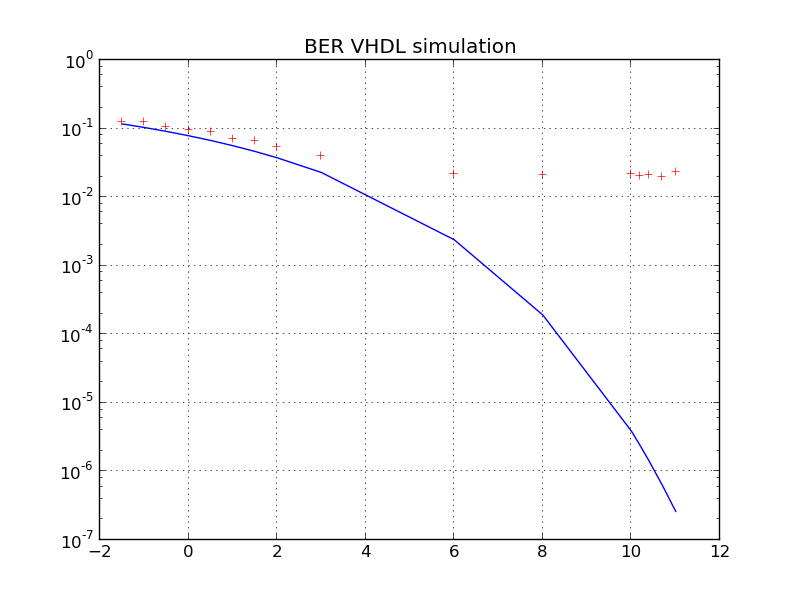
BER Simulation

As you can see I have a floor in my present design.

I'm asking if this floor is due to my fixed point system performance or it's an effect of the channel model.

Update[Solution]

Just fro add an update to the problem for future reference. The problem was in the parameters of the fixed-point FFT core used. The effects in the figure above are due to clipping, as stated from the helpful comments in this topic. Thank you for your support.

$\endgroup$
6
  • 1
    $\begingroup$ Can you show us the EbN0 curve? Does it show an error floor? Have you measured the signal-to-quantization-noise ratio before adding white Gaussian noise? $\endgroup$
    – Deve
    Commented Apr 12, 2013 at 6:54
  • $\begingroup$ @Deve I'll run the simulation and in few hours from now I'll be able to show the curve. I'm not measuring signal to quantization noise, the code above show the steps I'm using to add noise. I'm thinking about the results, with such a number of bits my results will agree with the theoretical curve? $\endgroup$ Commented Apr 12, 2013 at 11:52
  • $\begingroup$ Few hours? How many bits and EbN0s do you simulate? :) I just thought quantization noise could be the reason for your curve deviating from the expected result as the theoretical curve does not take quantization noise into account. $\endgroup$
    – Deve
    Commented Apr 12, 2013 at 15:02
  • $\begingroup$ @Deve try to simulate an ofdm system in VHDL and you'll understand this time :). I guess you're right about quantization noise and i'm runing a simulation for check this. $\endgroup$ Commented Apr 12, 2013 at 16:35
  • $\begingroup$ Yes, in that case I understand. That's why I use presimulated results of a VHDL transmitter for further processing in another programming language. $\endgroup$
    – Deve
    Commented Apr 12, 2013 at 17:06

2 Answers 2

2
$\begingroup$

The effect you're observing is most certainly due to quantization errors. If your calculation of noise power was wrong you would get an offset between the simulated and the theoretical curve but not an error floor. The fact that it works fine with 32 bit resolution supports that hypothesis. You can analyze the output signal of your VHDL transmitter in order to find out whether it's already corrupted. There are several things I would consider:

  • Calculate the BER without channel (back-to-back). It should be zero but from your diagram I guess it will be something around 0.02.
  • Plot the constellation diagram. You should see distinct points not "clouds".
  • Calculate the signal-to-quantization-noise ratio $\gamma_\mathrm{q}$. Let $a_{\nu k}$ be the complex value of subcarrier $\nu$ in OFDM symbol $k$ after mapping and $b_{\nu k}$ be the respective subcarrier value at the transmitter output (can be obtained by applying FFT to the tx output). Then $$ \gamma_\mathrm{q}=\frac{\sum_{\nu.k}|a_{\nu k}|^2}{\sum_{\nu.k}|b_{\nu k} - a_{\nu k}|^2} $$
$\endgroup$
4
  • $\begingroup$ Thank you @Deve! You're absolutely right! Your thoughts about the results are correct. I'm running some simulation with enough points to take the BER measure but the constellation presents the behaviour you said above. Now I have to realize how to improve the performance. $\endgroup$ Commented Apr 15, 2013 at 16:35
  • $\begingroup$ You're welcome. Do you use an IP core for the IFFT block and if yes, what output width does it have? $\endgroup$
    – Deve
    Commented Apr 15, 2013 at 17:03
  • $\begingroup$ I'm testing with 16b FFT core and truncating the output to 12b, this 12b input -> 16b processing -> 12b output. $\endgroup$ Commented Apr 15, 2013 at 17:13
  • $\begingroup$ If you're just discarding the LSBs then this is most probably the reason for the bad performance. I co-authored a paper about how to optimally reduce the word width of the IFFT output in an OFDM system. You can download it here: inue.uni-stuttgart.de/publications/pub_2012/… $\endgroup$
    – Deve
    Commented Apr 15, 2013 at 17:23
2
$\begingroup$

I do not think that your problem is noise quantization. Your curve shows that the BER levels out somewhere around EbN0 = 4, which means that that is around where the quantization noise equals the intended noise. That is unbelievable unless your signal power is really, really low. Q11 has 66 dB of dynamic range, so if you are using a significant portion of your dynamic range quantization noise simply should not be a factor at those EbN0's.

What I suspect is happening is that when you switch from 32 bits to 11 bits that affects all of the processing blocks of your VHDL design via "generic" statements, and so the data bit width throughout your design changes. I think some piece or pieces of your processing chain are not doing well at the lower bit widths.

$\endgroup$
5
  • $\begingroup$ I agree that with 12 bit resolution quantization shouldn't be a big issue but still quantization/clipping errors are the most probable reason for the observed behaviour. When you say some piece...are not doing well at the lower bit width isn't that just quantization noise due to an implementation that can certainly be improved? $\endgroup$
    – Deve
    Commented Apr 15, 2013 at 17:00
  • $\begingroup$ I also guess that you're talking about the same problem. @Jim I'm trying several parameter changes to test improve the performance of the core. $\endgroup$ Commented Apr 15, 2013 at 17:15
  • $\begingroup$ My point is that I think it is likely to be associated with quantization- I just don't think it has anything to do with the noise. $\endgroup$
    – Jim Clay
    Commented Apr 15, 2013 at 17:26
  • $\begingroup$ Ok, that's exactly what I think. $\endgroup$
    – Deve
    Commented Apr 15, 2013 at 17:30
  • $\begingroup$ Ok, but how far from the theoretical curve the system will be with QPSK and 12b? My first thought was that the performance should be close. $\endgroup$ Commented Apr 15, 2013 at 17:43

Your Answer

By clicking “Post Your Answer”, you agree to our terms of service and acknowledge you have read our privacy policy.

Not the answer you're looking for? Browse other questions tagged or ask your own question.