I'm trying to implement a QPSK Mod/DeMod system in C++. So far i have a bit generator that generates N bits and stores it into an array:
srand(time(0));
for (int i = 0; i < N; i++)
{
    bitstream[i] = rand() % 2;
}
Now I parse through the array to group bits of two and send those two bits to get modulated.
for (int j = 0; j < N; j++)
{
    if (bitstream[j] == 0 && bitstream[j + 1] == 0){ Dec_Num = 0; }
    else if (bitstream[j] == 0 && bitstream[j + 1] == 1){ Dec_Num = 1; }
    else if (bitstream[j] == 1 && bitstream[j + 1] == 0){ Dec_Num = 2; }
    else if (bitstream[j] == 1 && bitstream[j + 1] == 1){ Dec_Num = 3; }
}
The variable 'Dec_Num' is just the decimal representation of the group of two bits. The decimal number is what is sent to the QPSK Modulator function and is called with:
sig_no_noise = MOD_QPSK(Dec_Num);
The QPSK modulator function looks like:
complex<double> MOD_QPSK(int inc_bit){

if (inc_bit == 0){
    complex<double> QPSK_00(-sqrt(2)/2, -sqrt(2)/2);
    return QPSK_00;
    }
else if (inc_bit == 1){
    complex<double> QPSK_01(-sqrt(2)/2, sqrt(2)/2);
    return QPSK_01;
    }
else if (inc_bit == 2){
    complex<double> QPSK_11(sqrt(2)/2, sqrt(2)/2);
    return QPSK_11;
    }
else if (inc_bit == 3){
    complex<double> QPSK_10(sqrt(2)/2, -sqrt(2)/2);
    return QPSK_10;
    }
}
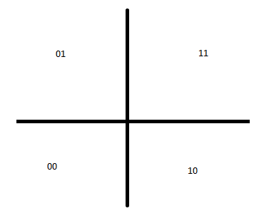
The QPSK modulator maps the decimal number to a constellation map using gray coding that looks like this:

Now I have normalized the signal power to one and thus each constellation point corresponds to (sqrt(2)/2 , sqrt(2)/2) or the negative depending upon which quadrant that point is in. The modulated signal is then sent through an AWGN channel to the receiver/demodulator. The AWGN channel is simulated by generating complex gaussians using the C++'s standard library normal_distribution function. Where the mean is 0 and the variance is the noise variance found from the user inputted signal to noise ratio in dB.
Variance generated from user-inputted SNR(dB):
cout << "Input SNR: ";
cin >> SNR;
SNR_lin = pow(10, SNR / 10);
var = 1 / (SNR_lin);
The complex gaussian noise is generated with:
default_random_engine generator;
normal_distribution<double> distribution(0, (sqrt(var)));
double number = distribution(generator);
double number1 = distribution(generator);
complex<double> AWGN_noise(number, number1);
So the modulated signal is added to this noise to simulate the signal going through an AWGN channel.
DeMOD_QPSK(sig_no_noise + noise);
The QPSK demodulator is then called. The QPSK demodulator calculates the euclidean distance between the signal and all four constellation points and finds the shortest distance. That constellation point is then returned. The QPSK demodulator looks like:
double DeMOD_QPSK(complex<double> reciv_sig_equal) //recv_sig with noise
{

double d[4];
double small;
int dec_bit, loc = 0;
double x2, y2;
x2 = real(reciv_sig_equal);
y2 = imag(reciv_sig_equal);
d[0] = sqrt(pow(x2 - (-sqrt(2) / 2), 2) + pow(y2 - (-sqrt(2) / 2), 2));
d[1] = sqrt(pow(x2 - (-sqrt(2) / 2), 2) + pow(y2 -   sqrt(2) / 2,  2));
d[2] = sqrt(pow(x2 - ( sqrt(2) / 2), 2) + pow(y2 - ( sqrt(2) / 2), 2));
d[3] = sqrt(pow(x2 -   sqrt(2) / 2 , 2) + pow(y2 - (-sqrt(2) / 2), 2));

small = d[0];
for (int j = 1; j<4; j++){
    if (d[j]<small){
        small = d[j];
        loc = j;
    }
}

if (loc == 0){ return dec_bit = 0; }
if (loc == 1){ return dec_bit = 1; }
if (loc == 2){ return dec_bit = 2; }
if (loc == 3){ return dec_bit = 3; }

}
Once the signal is demodulated into its decimal number, it has to be decoded once more to get it back to its original form of groups of two bits. This is done with this for loop:
decoded[j] = DeMOD_QPSK(sig_no_noise + noise);

    for (int m = 0; m < N; m++)
{
    if (decoded[m] == 0)
    {
        rec_bit[m] = 0;
        rec_bit[m + 1] = 0;
    }

    else if (decoded[m] == 1)
    {
        rec_bit[m] = 0;
        rec_bit[m + 1] = 1;
    }

    else if (decoded[m] == 2)
    {
        rec_bit[m] = 1;
        rec_bit[m + 1] = 0;
    }

    else if (decoded[m] == 3)
    {
        rec_bit[m] = 1;
        rec_bit[m + 1] = 1;
    }

}
The rec_bit array is the array that holds the received/demodulated data bits. The BER is then calculated by comparing the generated bits to the received bits:
for (int i = 0; i < N; i++)
{
    if (bitstream[i] != rec_bit[i])
    {
        BER_count++;
    }
}
BER = (BER_count / N);
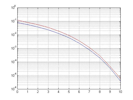
The problem is that when i go to compare my BER curve, for SNR's from 1 to 10, with the theoretical QPSK curve for the same range of SNR's, my curve is slightly off.

The red line is my QPSK BER curve, and the blue/lower curve is the theoretical curve. The theoretical curve was plotted/calculated with a small matlab code:
SNR_dB=[0 1 2 3 4 5 6 7 8 9 10];%In dB
SNR_lin=10.^(SNR_dB/10);%Converting to linear scale
bit_err=qfunc(sqrt(2*SNR_lin));
semilogy(SNR_dB,bit_err);
Any help/ideas/suggestions would be Greatly appreciated. I am an amateur at both C++ programming, and at signal processing. So please pardon my inefficient methods at modulation and my lack of technically correct terms.
