1
$\begingroup$

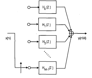
I have read many of the articles on the website regarding a polyphase decimating filter structure. I'm sure we are all familiar with the typical image shown in Fred Harris Multirate book and many other papers written on this topic below.

enter image description here

Say we have some transfer function H(z).. well the polyphase implementation works by decimating the filter into M parallel filters where fs/M is the desired output rate. The noble identities tell us we can pull the decimation through the filter stages... and hence the delays at the input are replaced by the commutator switch which effectively sends samples in at rate fs/M. Let N be the total number of taps in H(z)... the convenience of this is that we only need to filter with N/M taps per cycle which greatly reduces resources... ok I've done my homework.

Now my question. I have seen many implementations of this structure in code but I can't seem to find any implementations in simulink...specifically with what exactly is the commutator switch?

Here is an implementation that I have created in simulink... although it clearly doesn't work properly...Say I have some filter that was originally 120 taps and I now want an output rate that is 1/4 of the input rate... I decimate my filter into 4 sub filters and arrange into a parallel structure as shown below: enter image description here
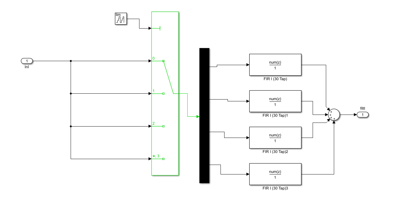
The switch on the input has a counter attached to it because I'm thinking that I can cycle between inputs at each clock edge to simulate the commutator...but then I need to demux the data into a branch that I want.. however this isn't working because the demux isn't controllable...

What am I doing wrong here? What is the block that simulates the commutator like shown in many of the block diagrams in the multirate papers we all know? I realize that it's a memoryless switch but which simulink block ?

$\endgroup$

2 Answers 2

1
$\begingroup$

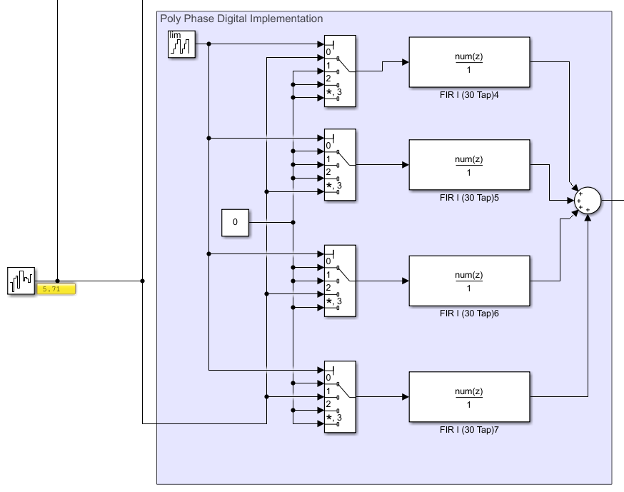
Just to follow up on this, I believe I figured out one way to do what I was looking for shown below...if anyone has any other ideas feel free to share too

enter image description here

$\endgroup$
7
  • $\begingroup$ Yeah so my question now is...how is this more efficient? I am sending data into the filters at a lower rate... so if I were to implement this in Verilog, what resources would I be saving? $\endgroup$
    – Samuel
    Commented May 21, 2020 at 23:58
  • $\begingroup$ The efficiency is gained in running the entire system at a lower rate. If you didn't do your decimation with a polyphase, you would be running your 120 tap FIR filter at the high rate- now you are running them all at the lower rate, so in terms of multiplications/second you are more efficient. And power is C(V^2)f, so to the degree your limited by dynamic power there will be a savings proportional to the change in frequency rate. $\endgroup$ Commented May 22, 2020 at 3:16
  • $\begingroup$ Thanks for responding Dan, and yes I agree that I am running my filtering operation at a lower rate now... but can that decrease the number of multiplies that I'm using, ie resources in an FPGA? Am I now effectively using 30 multiplies instead of 120 because I'm at a lower rate? I'm struggling trying to understand how the math works for that. $\endgroup$
    – Samuel
    Commented May 22, 2020 at 14:21
  • 1
    $\begingroup$ yes to the extent you can now time multiplex use of the multipliers (at the higher rate) So you have the option of saving power or space. $\endgroup$ Commented May 22, 2020 at 14:27
  • $\begingroup$ Yeah I was talking with a friend and he mentioned that I could interleave multiplies at the lower rate and timeshare to reduce space.... do you know of any good resources on how this works? I looked online and I can't seem to find anything that explains how this reduction works.. Thanks for your help so much! $\endgroup$
    – Samuel
    Commented May 22, 2020 at 14:33
1
$\begingroup$

For starters, there are Simulink blocks that support polyphase filtering, such as this one https://www.mathworks.com/help/dsp/ref/firdecimation.html.

If you still want to design your own block in Simulink, here's how to do it

1 - Insert downsampler blocks at the input of your 4 FIR filters, remember your FIR filters must run at slower rate compared to the original signal otherwise you lose the gain of polyphase filtering in t he first place. https://www.mathworks.com/help/dsp/ref/downsample.html

2 - Select the sample offset to be 0 for the first filter, 1 for the 2nd filter, 2 for the 3rd filter and 3 for the 4th filter.

3 - Sum the output of each FIR filter.

However, I'm not sure Simulink will be smart enough to share the resources between the 4 filters making your effort mostly pointless unless you simply want to learn.

You could code your own polyphase filter in Matlab and then use this Matlab function as Simulink block, I actually implemented a polyphase filter this way, because Simulink did not support 64-bit integers in its polyphase implementation.

Regards

$\endgroup$

Your Answer

By clicking “Post Your Answer”, you agree to our terms of service and acknowledge you have read our privacy policy.

Not the answer you're looking for? Browse other questions tagged or ask your own question.