0
$\begingroup$

i designed a sinusoidal pwm amplifier (3KHz to 20KHz) that regulates its output voltage reading the RMS value of output current.

The RMS is obtained squaring the signal sampled by AD converter @200KHz and then applyng a FIR filter with 120 TAPS.

The advantage of this method is that the settling time of the FIR (so the response to amplitude changing) is about 600us so i can correct the pwm duty every 1ms because the value is alread stable.

All works fine but the problem arises when an external signal is added to the signal the amplifier is generating.

Infact a signal of about 600Hz different from original one (i.e. amplifier generates 4950Hz and a 5550Hz signal is added as external noise) causes an oscllation in RMS measure makes the amplidifer works in wrong way.

Applying a bandpass FIR makes the response of FIR slower. I tried downsampling by a factor of 4 and make a FIR of 1KHz bandwith but the fastest settling time i obtained was about 5ms that is too much because i've to regulate every 1ms.

Have you any idea or advice? Is there any algorithm to cancel unwanted component maintaing fast RMS response?

Thank you . Let me know.

$\endgroup$
3
  • $\begingroup$ There are faster ways to estimate the amplitude. If I have the time tomorrow I will post it. Basically, you need a quadrature signal generator locked to the frequency of your generated signal with an alpha-beta transform and you will be able to estimate the amplitude of your generated signal faster and also reject the "noise" signal. $\endgroup$
    – Ben
    Commented Nov 25, 2019 at 3:26
  • $\begingroup$ Very interesting.... i'll wait for your post $\endgroup$
    – franticSE
    Commented Nov 25, 2019 at 19:33
  • $\begingroup$ @Ben i answered to you comment but perhaps the tag didn't work. I had to post an ANSWER because i had to add some figures...let me know... $\endgroup$
    – franticSE
    Commented Nov 29, 2019 at 13:07

2 Answers 2

2
$\begingroup$

I believe you are running into stability issues in an output power control loop design.

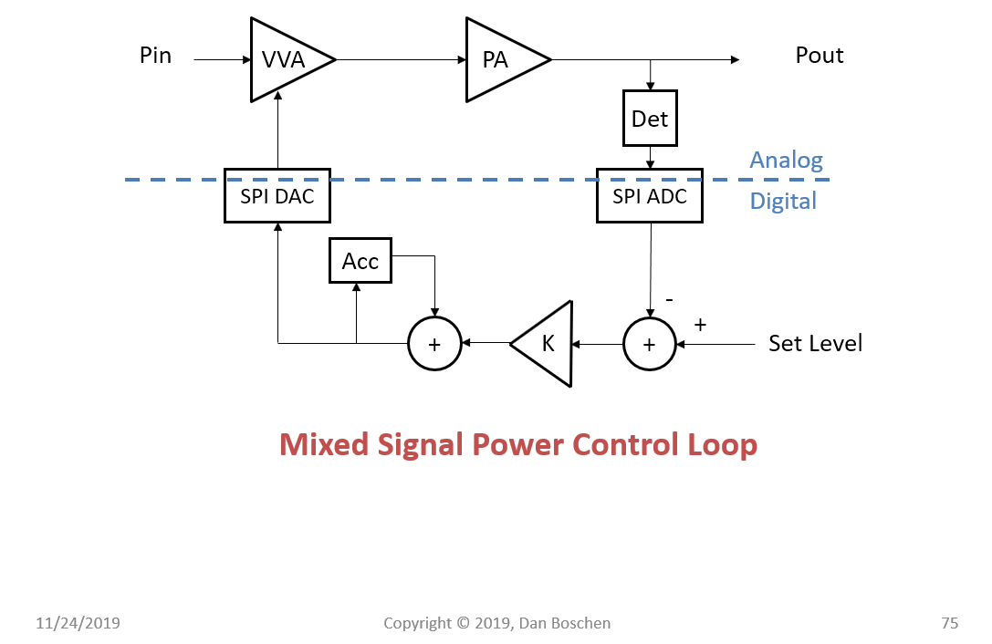
See below a diagram of similar power control loops that I have implemented, where for stability reasons any filtering in the loop is minimized and only done with the loop filter itself which is designed for stability. The noise you are trying to filter gets filtered by the loop bandwidth itself.

The diagram below is very simple to implement (first order type 1 loop), where the accumulation of the derived error sets the loop bandwidth by adjusting K. Make K very small for a long averaging time and better filtering but slower response.

power control loop

Ultimately if the trade of filtering versus response time with a simple implementation like shown above is insufficient, you can change the loop filter to be a PID loop. This would more complicated and require more understanding of control loop design and a more detailed loop model but give you better performance in noise filtering versus response time. Essentially the accumulator (I) shown above would also be summed with a proportional path (P) and a derivative path (D) all with different gain weights and followed by a second accumulator for a second order type 2 PID loop.

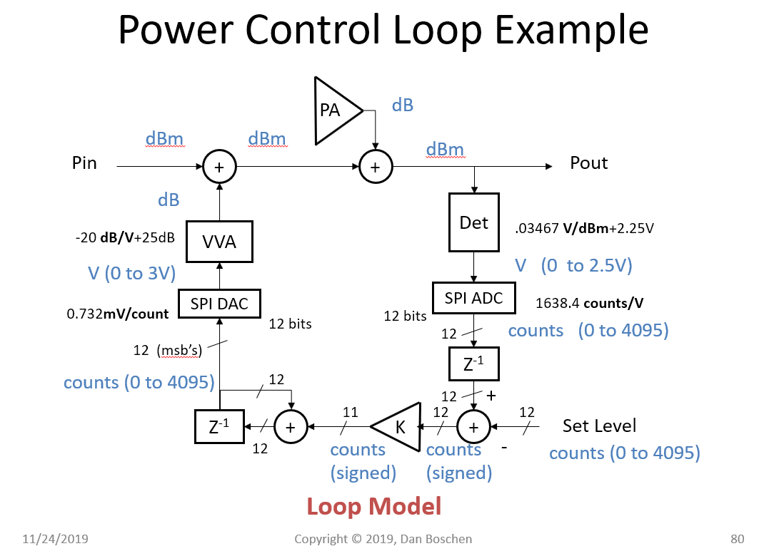
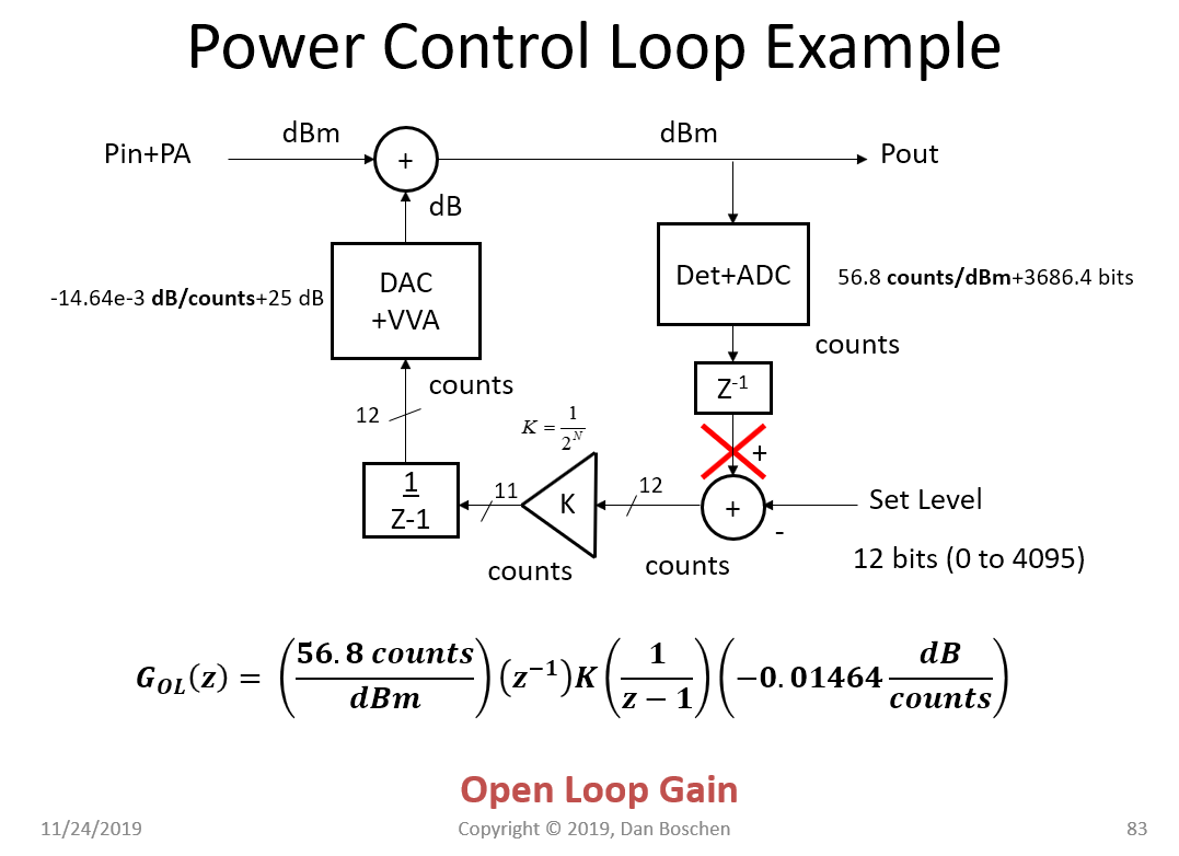
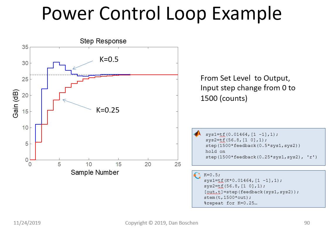
Once a loop model is created, the modeling of the response time and effective filtering is very straightforward with tools such as Matlab, Octave or Python. As an example of the design process, below shows the loop model for the Power Control Loop given by the block diagram above along with the modeled response times versus K:

Loop Model

Open Loop Gain

The above case results in an open loop gain given by:

$$G_{OL}(z) = \frac{0.83155K}{z(z-1)}$$

Below demonstrates given the Matlab and Octave code snippets how simple it is once the model is established to create the step response for the loop. Note the overshoot indicative of a higher order loop- this is due to the parasitic $z^{-1}$ in the digital loop implementation, and with a high enough K the loop will be unstable (unlike a true first order type 1 loop). Similarly the noise bandwidth, etc is easily established and optimized.

step response

$\endgroup$
7
  • $\begingroup$ set level in my application is a sinusoidal signal... i don't know if it is so easy use that kind of feedback. I tried with PID in the past but i couldn't make it work. Then I chose a simpler way, that is to minimize the difference between rms read and desirable and tuning with the change of duty... duty changes until the difference of two rms is near zero.... $\endgroup$
    – franticSE
    Commented Nov 24, 2019 at 19:49
  • $\begingroup$ What you are doing is a control loop--- PID is complicated if you are not intimately familiar with control loop design. But your "simpler way" of minimizing the error is exactly what a control loop is doing--- your change of duty cycle is the control parameter and your difference is the error signal. $\endgroup$ Commented Nov 24, 2019 at 19:55
  • $\begingroup$ You can set level with a sinusoidal signal with this kind of feedback- ultimately your loop bandwidth needs to be wider than the sinusoidal signal if you want the loop to keep up with it (AM modulate your signal). So in your case you can do the same thing (the simpler first order type 1 loop) by accumulating your error and then using the scaled accumulated output to control your duty cycle. Adjust K to vary your loop bandwidth. You can add additional high frequency filtering in the loop but it will soon make it unstable- $\endgroup$ Commented Nov 24, 2019 at 19:59
  • $\begingroup$ At that point for further improvement you could go to a 2nd order Type 2 PI loop (adding an proportional path summed with the integrator output followed by another integrator) and then perhaps further improvement with a PID beyond that depending on the loop dynamics. $\endgroup$ Commented Nov 24, 2019 at 20:00
  • 1
    $\begingroup$ @Ben I think you meant to comment on the OP's question--- my answer doesn't suggest an FIR filter but a simple accumulator (or other related loop filter). $\endgroup$ Commented Nov 25, 2019 at 3:18
0
$\begingroup$

@Ben I try to implement your idea and actually the amplitude of the signal is obtained starting from two components in quadrature.

But when i add an external signal, of the same amplitude, to my input the result is an oscillating signal

How can i reject the noise?

$\endgroup$

Your Answer

By clicking “Post Your Answer”, you agree to our terms of service and acknowledge you have read our privacy policy.

Not the answer you're looking for? Browse other questions tagged or ask your own question.