The region of convergence (ROC) of the $\mathcal{Z}$-transforms of a step-modulated sinusoid
$$x[n]=\sin(\omega_0n)u[n]\tag{1}$$
is the region $|z|>1$. The ROC of the transfer function
$$H(z)=\frac{b_0+b_1z^{-1}}{1- z^{-1}}\tag{2}$$
also equals $|z|>1$ (assuming a causal system). Consequently, multiplying the two transforms doesn't pose any problem, and the result also converges for $|z|>1$.
As an example, let's compute the response $y[n]$ of the system $(2)$ to the input $(1)$. For the sake of simplicity we assume $b_0=1$ and $b_1=0$ in $(2)$. First, we compute the response to
$$\tilde{x}[n]=e^{j\omega_0n}u[n]\tag{3}$$
The $\mathcal{Z}$-transform of $(3)$ is
$$\tilde{X}(z)=\frac{1}{1-e^{j\omega_0}z^{-1}}\tag{4}$$
The $\mathcal{Z}$-transform of the response $\tilde{y}[n]$ is given by
$$\begin{align}\tilde{Y}(z)&=\tilde{X}(z)H(z)\\&=\frac{1}{1-e^{j\omega_0}z^{-1}}\cdot \frac{1}{1-z^{-1}}\\&=\frac{A}{1-e^{j\omega_0}z^{-1}}+\frac{A^*}{1-z^{-1}}\tag{5}\end{align}$$
with
$$A=\frac{1}{1-e^{-j\omega_0}}=H(e^{j\omega_0})\tag{6}$$
The inverse $\mathcal{Z}$-transform of $(5)$ is
$$\tilde{y}[n]=H(e^{j\omega_0})e^{j\omega_0n}u[n]+H^*(e^{j\omega_0})u[n]\tag{7}$$
The response to the step-modulated sinusoid $(1)$ is easily obtained from $(7)$ by taking its imaginary part:
$$\begin{align}y[n]&=\textrm{Im}\big\{\tilde{y}[n]\big\}\\&=\big|H(e^{j\omega_0})\big|\sin\big(\omega_0n+\arg\left\{H(e^{j\omega_0})\right\}\big)u[n]\\&\qquad -\textrm{Im}\big\{H(e^{j\omega_0})\big\}u[n]\tag{8}\end{align}$$
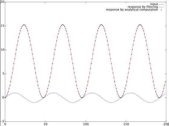
The first term in $(8)$ is the steady-state response, and the second term is the transient response, which doesn't decay because of the system's pole at $z=1$.
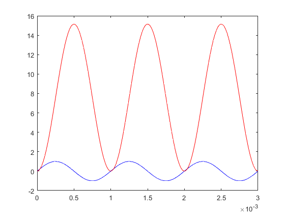
So the output has a DC component due the imaginary part of $H(e^{j\omega_0})$. Note that this is no contradiction with the linearity of the system, because the input signal is not a single spectral line but it has a continuous spectrum extending down to DC due to the sinusoid being switched on at $n=0$. This DC value of the input's Fourier transform triggers the system's eigenfrequency, which is a DC component. Note that this always happens with LTI systems: the output may contain oscillations at frequencies that are only determined by the system, not by the input signal. However, unlike in the given example, usually these transients decay because most of the time we consider asymptotically stable systems.
I slightly modified your Matlab/Octave script and added the analytical result $(8)$ for comparison. The analytical result is identical (up to numerical accuracy) to the result obtained by filtering:
fs = 48000;
f0 = 1000;
w0 = 2*pi*f0/fs;
N = 200;
n = 0:N-1;
x = sin(w0*n);

bd = [1 0];
ad = [1 -1];
yi = filter(bd, ad, x);
figure;
plot(n,x,'b'); hold on;
plot(n,yi,'r')

% analytical computation
A = 1 / ( 1 - exp( -1i*w0 ) );
y2 = abs(A) * sin( w0*n + angle(A) ) - imag(A);

plot(n,y2,'k.'), hold off
legend('input','response by filtering','response by analytical computation')


