I have an existing zero-delay feedback (ZDF) 2-pole state variable filter implementation (along the lines of the theory presented in VA Filter Design by V. Zavalishin), and I wish to determine the frequency response so that I can plot it. My usual approach with other filters (e.g. biquads) has been to determine the difference equation by inspection, apply the Z-transform, and then substitute $z=e^{j\omega}$ and plot phase and magnitude against $\omega$ from $0$ to $\pi$.
However I am having difficulty determining the difference equation of this filter.
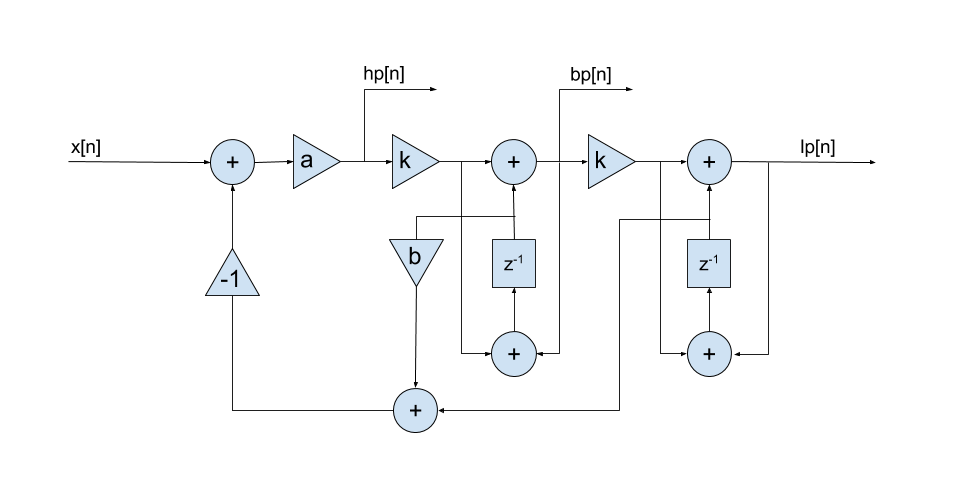
Here is a diagrammatic representation of the implementation I have:
Here's the implementation of an iteration, corresponding to a single input sample, in pseudo-code. Fs is the sample rate, F is the filter frequency of interest, R is the resonance, x is the input sample, and lp, bp, hp represent the low, band and high-pass outputs respectively:
# z1 and z2 contain state from previous iteration

k = tan(pi / Fs * F)
b = R + k
a = 1 / (1 + b * k)

hp = (x - (z2 + z1 * b)) * a
x1 = hp * k  # temporary
bp = x1 + z1
x2 = bp * k  # temporary
lp = x2 + z2

z1 = x1 + bp
z2 = x2 + lp
For analysis, I assign $v[n]$ to be the output of z1, and $w[n]$ to be the output of z2. From this I am able to determine by inspection the following equations:
$$hp[n] = x[n] - (b.v[n] + w[n])$$ $$v[n] = k.hp[n-1] + bp[n-1]$$ $$w[n] = k.bp[n-1] + lp[n-1]$$ $$bp[n] = k.hp[n] + v[n]$$ $$lp[n] = k.bp[n] + w[n]$$
I'm not sure how to handle such a system of equations algebraically. For example, if I wish to analyse the low-pass response, then I will need to determine a difference equation for $lp[n]$ in terms of $x[n]$. However I have not had success manipulating these equations by rearrangement and substitution even with the help of the Z transform. Is it possible to do this or are there too many unknown variables?
If an algebraic solution is impossible, is there an alternative method to determine the frequency response of this filter?
