See pages 5 and 6 and the plots on the following pages specific to number of samples per symbol in this very helpful reference by Ken Gentile on designing RRC pulse shape filters:
http://www.analog.com/media/en/technical-documentation/application-notes/AN-922.pdf
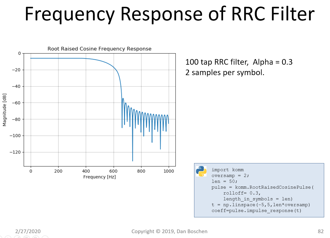
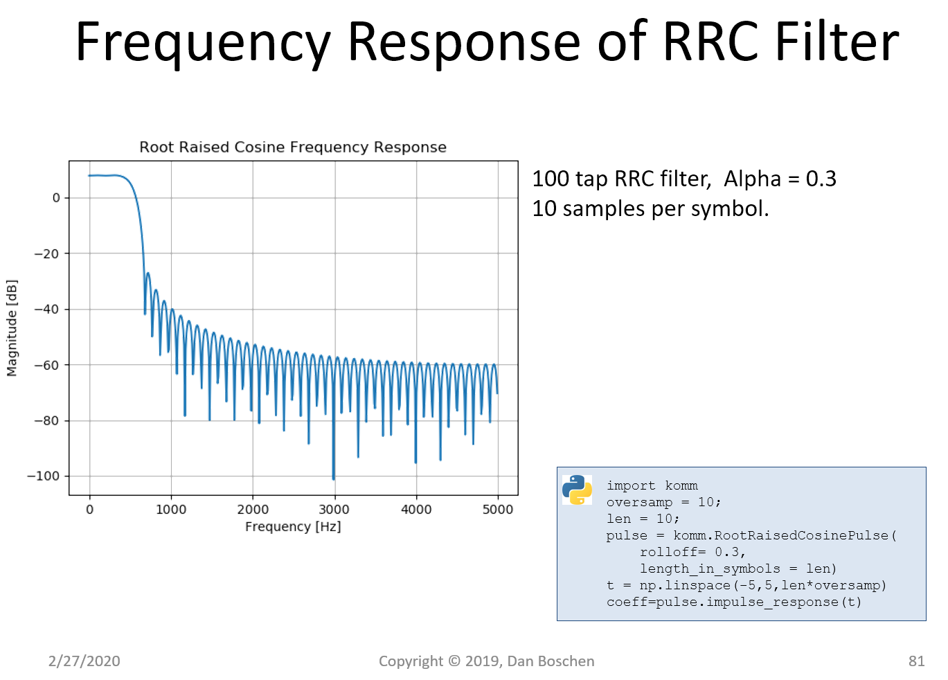
An example I have previously done shows the consideration of filter length (how many symbols does the filter span) and number of samples per symbol. The top plot shows a 100 tap RRC filter with only 2 samples per symbol and the lower plot it is the same number of taps but 10 samples per symbol.


Observe the following key points that illustrate some of the important considerations involved: With 2 samples per symbol the filter impulse response extends further in time. This results in a greater stop band attenuation for the same filter roll-off factor (Alpha) and complexity (number of taps). The difference is particularly dominant close to the band edge in the area of 700 Hz in the plots. In the figures shown we see that we get approximately 70 dB of attenuation for 2 samples per symbol but only approximately 35 dB of attenuation for 10 samples per symbol. However the overall frequency of the digital spectrum is most constrained for 2 samples per symbol; this is resolved with subsequent up-sampling or consideration elsewhere in our overall system design. As long as those considerations are properly addressed, according to Nyquist sampling theorem we will achieve the full integrity of our RRC filter design (with only 2 samples per symbol!).
In the second case, because of the higher number of samples per symbol, with the same number of filter taps (complexity) the impulse response of the filter does not extend as far in time, and is therefore truncated earlier. This degrades overall performance as visible here with the inferior filter rejection. However the greater overall digital frequency spectrum is wider.
An efficient design would choose to do two samples per symbol for such a "shaping" filter and then upsample to the bandwidth needed to be compatible with the analog design or other bandwidth considerations, since the upsampling filter design would be relatively simpler. Also to be considered for many applications is a polyphase RRC upsampling filter structure. In this case we would choose an even number of taps and incorporate the upsampling as described further in this response: How to implement Polyphase filter?
Keep in mind, as explained further in this post: Why root raised cosine filter can eliminate intersymbol interference (ISI) ? the entire motivation to do RRC filtering is spectral efficiency: hence regulatory requirements (spectral mask) will often dictate the rejection ultimately needed in the RRC filter (as long as subsequent analog stages, in particular the power amplifier, maintain sufficient linearity to not undo the shaping we so carefully applied...resulting in "spectral regrowth!).


