In the Fourier domain, the frequency increases with the distance from origo. So an ideal low-pass filter in the Fourier domain is shaped like a disk centered at the origo.
Here they work with only one quadrant of the Fourier domain. Therefore, they create a pie-shaped mask H for the quadrant by computing the Euclidean distance from the quadrant corner and store the distance values in D. The mask H is then chosen as all elements in D with values less than the parameter P (which is the radius of the disk).
So the answer to your question(s) is that the distance computation helps the method compute the filter shape. The key is that a constant Euclidean distance from a point defines the shape of a circle, and all elements inside that circle form the disk that is used as filter mask.
So, naturally, after filtering, only the low-frequency components of the image are left in the Fourier domain. Then the low-pass filtered image is retrieved by inverse transforming the filtered image back from the Fourier domain to the spatial domain.
EDIT
Here is an illustrated example to clarify the answer.
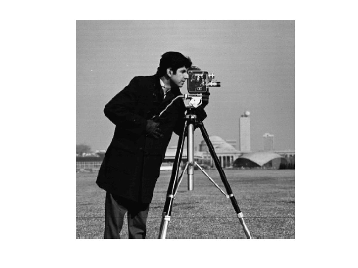
A typical way of illustrating filtering in the Fourier domain is to show the input image.
Then we show the Fourier transform of the image.
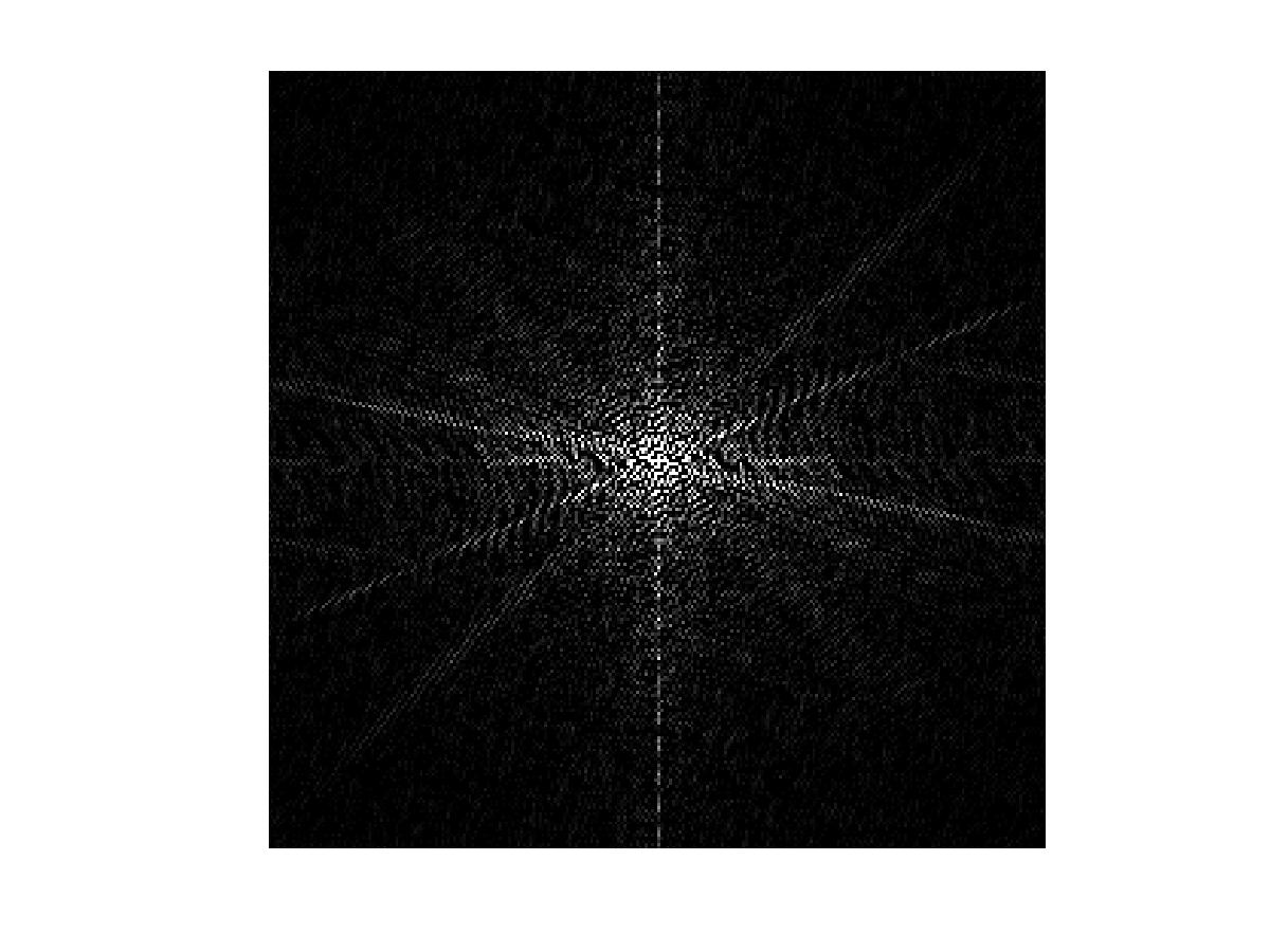
Here the origo of the Fourier space is in the center. Since the frequencies increase with the distance from origo, the ideal filter is a disk with its center at the origo. Here we see the disk.
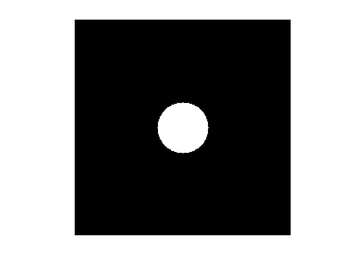
The disk radius is the input parameter P. We use the disk to filter the image by multiplying the filter with the transformed image. We then get the filtered transform.
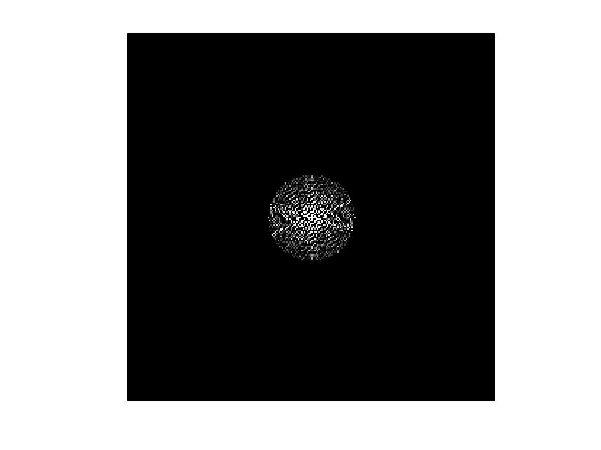
To get the filtered image we take the inverse transform of the filtered result.
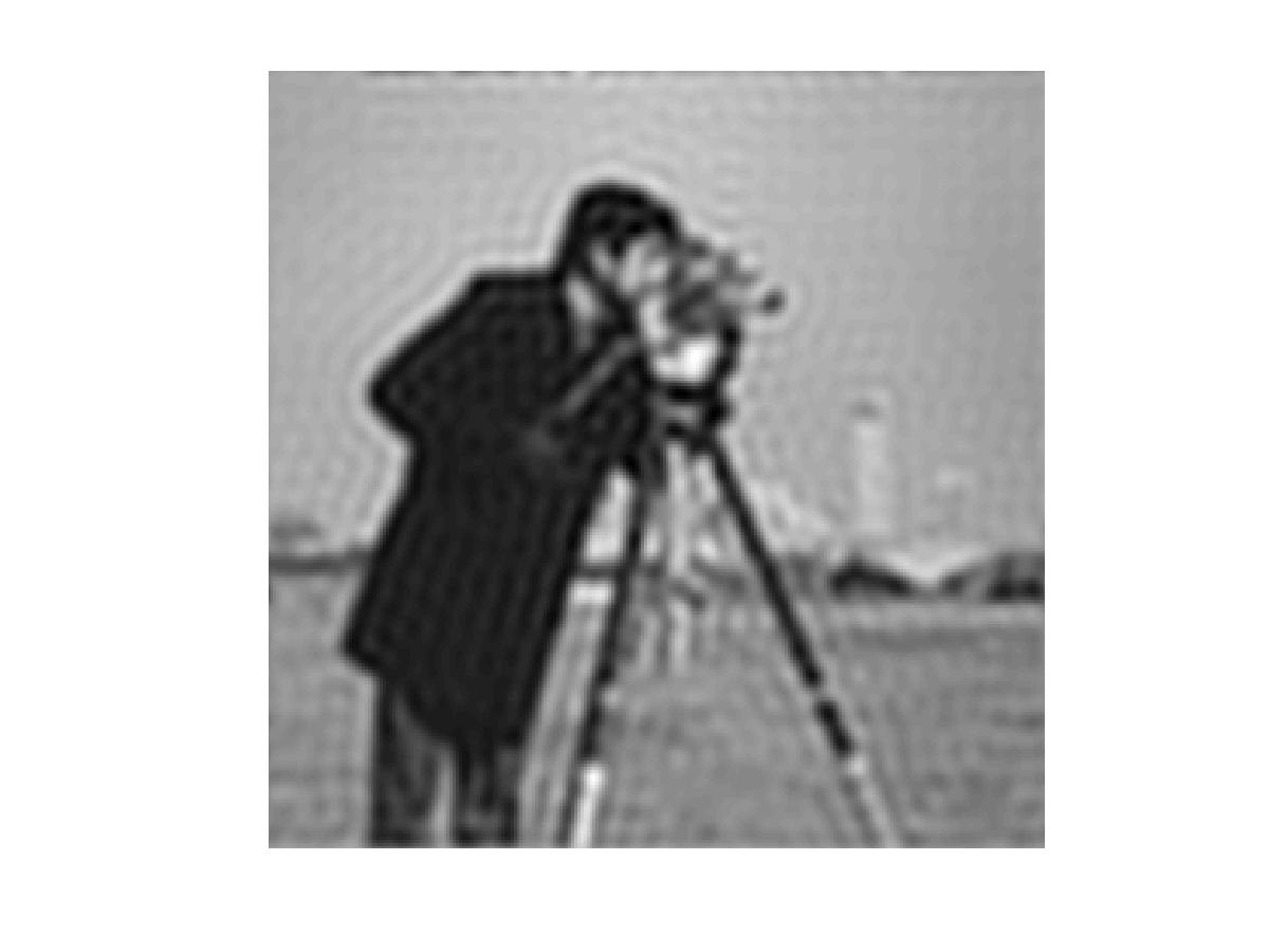
So far so good. As I said, this is usually how low-pass filtering in the Fourier domain is explained.
Now what I was trying to explain when talking about quadrants of the Fourier domain, which got a bit confusing, is that the result from the Fourier transform in the MATLAB code provided does not have origo centered as in the second image in the example above (the image showing the unfiltered Fourier transform).
Instead the result from the Fourier transform F=fft2(double(f)) looks like this (we refer to it as the transform image).
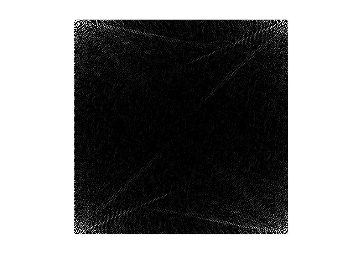
This means that since the filter is a disk with its center in origo, the disk must be placed in the corner of the transform image. Since the Fourier transform is cyclic, the filter should wrap around to cover all four corners of the transform image.

Here is where the distance matrix D comes in. It is used to compute the filter mask above. D is computed by taking the Euclidean distance from each corner (using a neat trick with meshgrid). So Dis the Euclidean distance map looking like this,
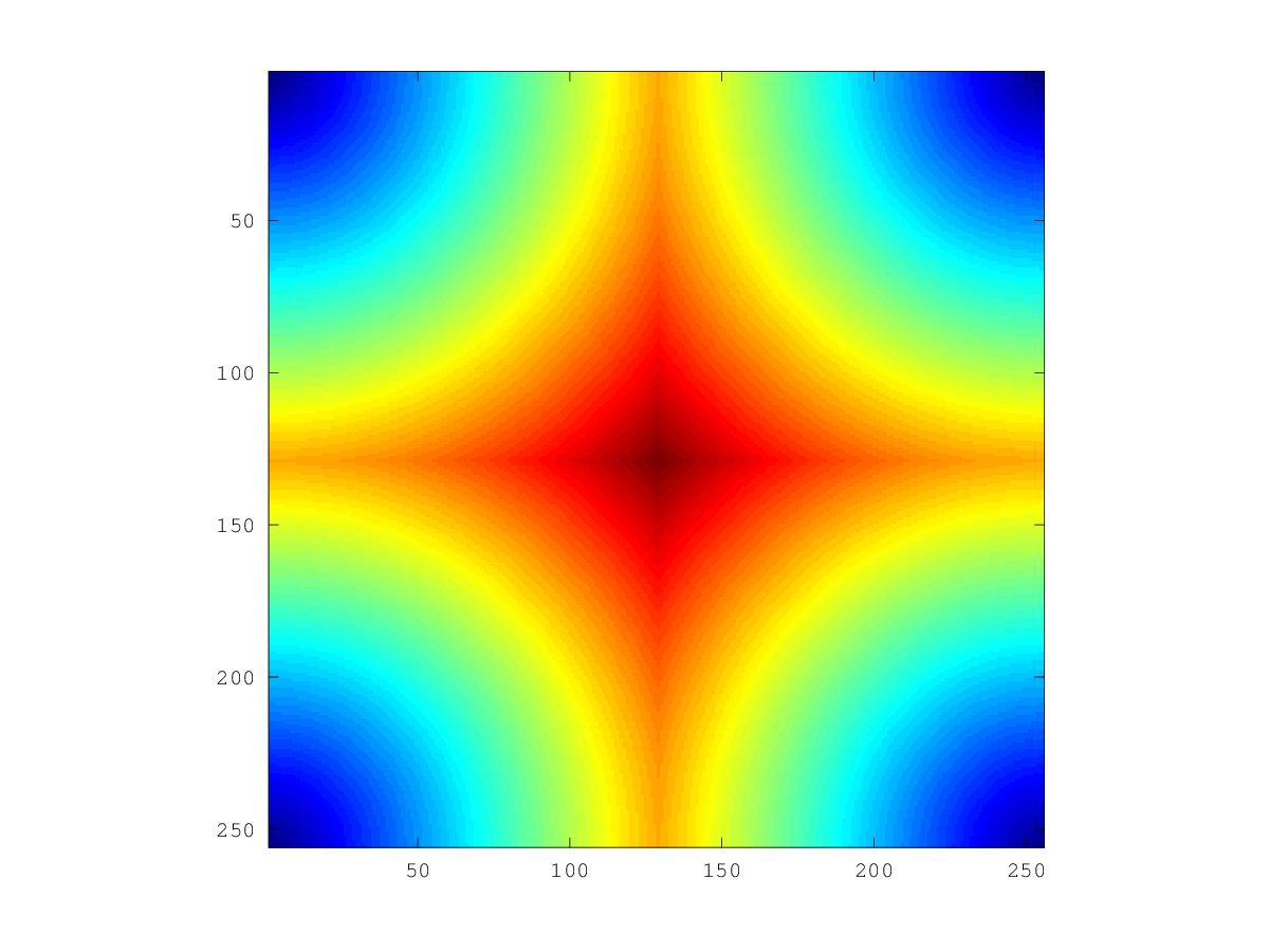
where blue values represent low distances and red values represent high.
% Top left corner of D
0.00000   1.00000   2.00000   3.00000   4.00000   5.00000
1.00000   1.41421   2.23607   3.16228   4.12311   5.09902
2.00000   2.23607   2.82843   3.60555   4.47214   5.38516
3.00000   3.16228   3.60555   4.24264   5.00000   5.83095
4.00000   4.12311   4.47214   5.00000   5.65685   6.40312
5.00000   5.09902   5.38516   5.83095   6.40312   7.07107
The filter mask can therefore simply be acquired by selecting the elements in D that have a distance value less than or equal to P.
The rest of the code works as in the example described above. That is, the filter mask is multiplied by the transform image, and the result is inverse transformed to get the low-pass filtered image.
I hope this clarifies what role the distance computation has for creating the filter.


