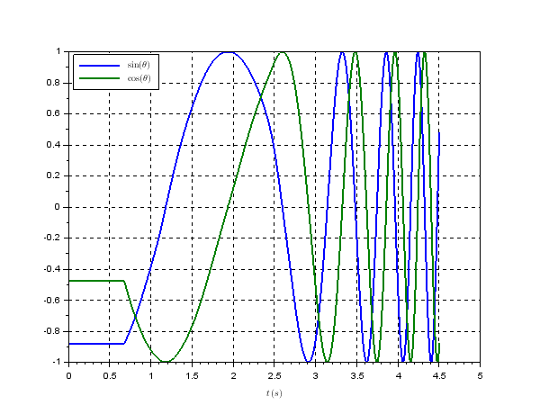
Instantaneous frequency is the time derivative of phase. Since the OP already has the analytic signal representation of the chirp, every sample can easily be used for the frequency estimate (unlike zero crossing frequency estimators for real signals, where the better solution in that case is to use the Hilbert Transform to arrive at this point that the OP already has).
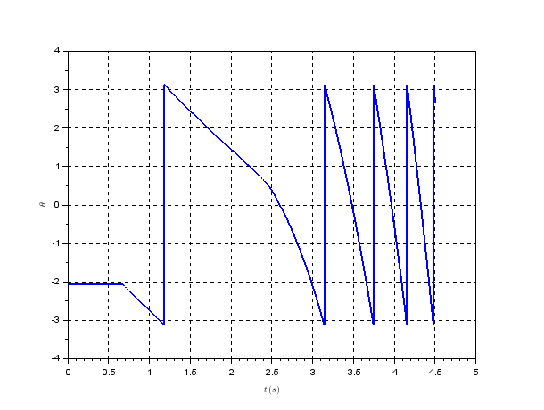
The concern with using the derivative that was raised in the comments under the question is the discontinuity in phase. This is resolved by unwrapping the phase first and then use the derivative to compute the instantaneous frequency. Rick Lyons has a nice blog post on alternate discrete time derivative computations that can have better noise performance (considering the high frequency noise enhancement of a true derivative).
If using MATLAB, Octave or Python phase unwrapping is a built in function as np.unwrap(phase) in Python or unwrap(phase) in MATLAB/Octave. Otherwise phase unwrapping can be done manually by detecting the discontinuity (easily done since the step change far exceeds any other sample to sample variation).
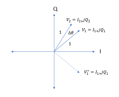
Also note that for small phase steps and normalized amplitude, the frequency can be well approximated using a cross product frequency discriminator, where $freq \propto \text{IM}\{x[n-1]^*x[n]\}$ for complex samples due to the small angle approximation $\sin(\theta) \approx \theta$. We can see how $\sin(\theta)$ is the imaginary component for the conjugate product of two successive complex samples from the equations developed below where the prior sample $x[n-1]$ is the complex signal represented as $I_1+jQ_1$ and the current sample $x[n]=I_2+jQ_2$:
$$(I_1-jQ_1)(I_2+jQ_2)$$
$$= (I_1I_2+Q_1Q_2) + j(I_1Q_2-Q_1I_2)$$
Given the frequency as a change in phase over a change in time, knowing the time step between the complex samples, if sufficiently oversampled (to maintain the small angle approximation) the frequency is given as:
$$f = \frac{\Delta \theta}{\Delta T} \approx f_s(I_1Q_2-Q_1I_2) $$
How this works is very intuitive when you consider the complex tone as a rotating phasor on the complex (IQ) plane as given in the diagram below. $V_1$ is the sample of the waveform at a particular sample in time and $V_2$ represents the subsequent sample due to the frequency of the waveform. When you multiply phasors, the angles add, thus by conjugating the first phasor, the resulting product will be the difference between the absolute angles of each phasor. This will work regardless of position in the IQ plane (no discontinuity) and for small angles, the angle solution reduces to the imaginary component of the result. If the amplitude is not normalized, the result must be divided by the product of each amplitude (which is normalization).


