2
$\begingroup$

It is known that in FFT time and frequency resolution are inversely related if FFT resolution is increased then time resolution will decrease. However is it possible to overcome issues in time resolution by methods such as overlap FFT etc. and also how much is theoretically possible given all other parameters such as sampling frequency are fixed?

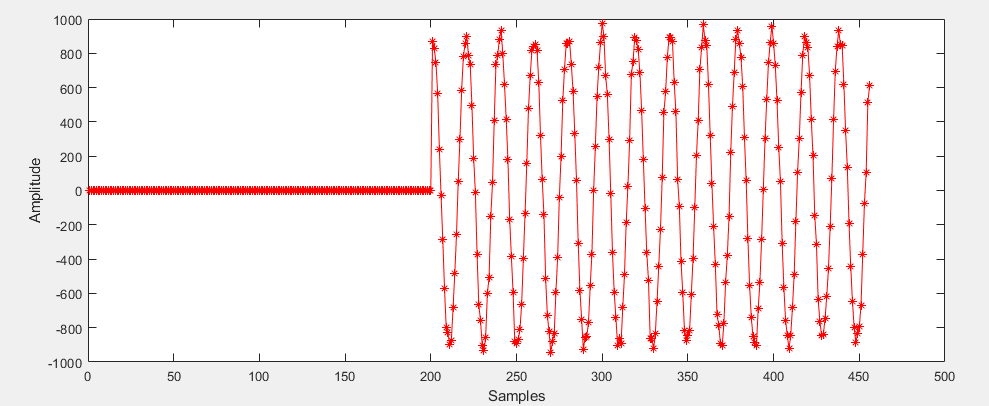
Edit: Visualization of the problem shown below:

enter image description here

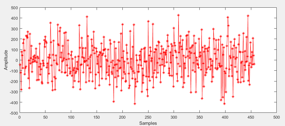
STFT of the above signal is to be performed and the start of the pulse is to be estimated to the highest possible accuracy. Also, when significant noise is added the signal above, the resulting signal in time domain looks like below:

enter image description here

Now the presence of the signal can be determined by taking an FFT when the overlap window starts sliding left beyond the 200th sample, but is it still possible to determine where exactly the signal started even though it is buried in noise?

$\endgroup$
4
  • $\begingroup$ i don't understand what is your question!? the resolution in Fourier domain is related to the length of your signal not the sampling frequency (resolution in time domain) $\endgroup$
    – Mohammad M
    Commented Mar 1, 2022 at 21:17
  • $\begingroup$ The frequency resolution of the FFT is Fs/N where as the time duration of the FFT frame is its inverse N/Fs. If Fs is increased then length of window will be shorter in time domain. $\endgroup$
    – malik12
    Commented Mar 2, 2022 at 6:41
  • $\begingroup$ Ok, but still i dont get your question. please tell me what do you have and what do you want to obtain from that. $\endgroup$
    – Mohammad M
    Commented Mar 2, 2022 at 7:42
  • $\begingroup$ Basically I want to know if it is possible to get good time accuracy for signal edges by increasing overlap percentage and if so how much accuracy is theoretically possible or if there are any other methods for this? $\endgroup$
    – malik12
    Commented Mar 2, 2022 at 10:26

4 Answers 4

3
$\begingroup$

Yes. Windowing will decrease the frequency resolution and therefore increase time resolution. The resolution bandwidth as the inverse of time resolution is well tabulated in the classic paper by fred harris "On the Use of Windows for Harmonic Analysis with the Discrete Fourier Transform". Further you can compute the resolution bandwidth for any window directly with the following formula:

$$B = N \frac{\sum(w[n]^2)}{(\sum w[n])^2}$$

Where $B$ is the equivalent noise bandwidth in bins, and $w[n]$ are the window values, equal in length to the FFT.

The OP has clarified that the objective is to determine the starting edge of a pulse in time. I assume the pulse is bandwidth constrained in the presence of other significant noise or interference in other frequencies and hence the motivation to use the FFT as an approach to band filtering the signal of interest. I would suggest alternatively time domain techniques rather than frequency domain for purpose of determining time domain features. Specifically consider using a time-domain band pass filter to select the frequency range of interest and then from the filtered result in the time domain the time location for the start of the pulse can be easily determined with threshold detection on the pulse amplitude.

Further details, considerations and suggestions with that approach are as follows:

Use a linear phase filter so that the introduced delay of the filter can be easily removed / compensated for and will not cause any signal distortion (for a linear phase filter the delay is simply half the number of coefficients).

The bandwidth of the filter will effect the rise time of the resulting pulse, so there will be a trade of time accuracy and noise. For example, if the pulse itself was rectangular, this would require infinite bandwidth, which would also introduce the maximum amount of noise to the point where we may not be able to detect any signal in the noise. As we reduce the bandwidth, rise time will increase and noise will decrease, but the slower rise time will give us more uncertainty in the actual time event of what we refer to as "start of pulse" in the presence of noise. As a guideline, the relationship between the 10% to 90% rise and fall time to bandwidth is:

$$t_r = \frac{0.35}{BW}$$

Where $t_r$ is the 10% to 90% rise time (or 90% to 10% fall time) in seconds, and $BR$ is the bandwidth in Hz. This is specifically for a first order system, but will approximately hold very well for higher order systems as well.

$\endgroup$
13
  • $\begingroup$ But wouldn't windowing decrease amplitude at frame boundaries and would make it difficult to locate where exactly the signal edge was located? $\endgroup$
    – malik12
    Commented Mar 2, 2022 at 6:06
  • 1
    $\begingroup$ In the FFT we are seeing the average for each frequency component within the window over that time interval. By windowing we are weighting the average toward the center and thus able to discern frequency change versus time with higher time precision than we would otherwise be able to do. $\endgroup$ Commented Mar 2, 2022 at 11:45
  • 1
    $\begingroup$ Thank-you for referring to fred in his preferred style. :-) $\endgroup$
    – Peter K.
    Commented Mar 3, 2022 at 23:20
  • 1
    $\begingroup$ @malik12 the low SNR implies over the full bandwidth. Even with the FFT if you had negative SNR (on a per bw sense) you would not be able to detect the signal. The FFT is just a narrow band filter for each tone of interest. A bandpass filter will give you the same "processing gain" with regards to SNR and noise, and more effectively than an FFT. Your optimum filter (if the noise was white) would be a matched filter, and for other situations your optimum filter would specifically reject the noise where the noise is occurring if it is colored. $\endgroup$ Commented Mar 11, 2022 at 12:40
  • 1
    $\begingroup$ @malik12 sure- you could use the FFT or a generalized filter bank. What you could consider is a streaming solution where you shift your FFT block one sample at a time, with windowing as I described. This is basically a filter bank implementation. $\endgroup$ Commented Mar 14, 2022 at 12:33
2
$\begingroup$

is it possible to overcome issues in time resolution by methods such as overlap FFT

Yes and no. You can certainly increase time resolution by having more overlap, but this results only in interpolation but not additional information

$\endgroup$
2
  • $\begingroup$ But would that be useful if I were interested in locating the edge of signal within that frame? $\endgroup$
    – malik12
    Commented Mar 2, 2022 at 6:08
  • 1
    $\begingroup$ It may or it may not. overlapping is one method of interpolation. There are many others (splines, pchips, linear, etc. ) , Choose the method that best fits your problem $\endgroup$
    – Hilmar
    Commented Mar 3, 2022 at 9:11
1
$\begingroup$

The answer depends on your assumptions and facts about the signal, and what you really require when using the word "resolution". If the signal is stationary with isolated spectral peaks surrounded by a significantly lower noise floor, then it is possible to increase spectral peak estimation resolution if those assumptions are met. But you will get bogus results if those requirements are not met (e.g. won't work if you are trying to resolve closely spaced spectral peaks, highly varying-in-time spectrum, or spectrum of interest buried in noise).

If the signal meets the above requirements, then you can interpolate spectral peaks between FFT result bins from a single FFT using Sinc (or window-transform) interpolation. Or you can use phase vocoder analysis or spectrum reassignment algorithms with an overlapped set of FFT results to increase spectral peak estimation precision (such as for a higher resolution spectrogram plot). The magnitude and phase differences between overlapped FFT frames provides the information gain (assuming spectral stationarity across those overlaps).

For more time resolution from a given FFT length, you can always use a narrower window, either a window the same length with a narrower main lobe, or a shorter window with zero-padding on one or both sizes. But with narrower windows, if you don't want to lose information or miss events between FFT frames, you may need more frame overlap.

If you can't overlap frames more in your original capture, but still need more time resolution, you could always IFFT each frame, make copies, and then FFT each copy using different sub-offsets of narrower windows.

As for how much is theoretically possible, for a single pure sinusoid in zero noise you can estimate all its parameters using only 3 or 4 non-aliased samples, with the resolution error bounded by arithmetic and sampling quantization.

$\endgroup$
1
  • $\begingroup$ Thanks for your detailed response. Basically what I hope to find out is where exactly within my FFT frame does the signal start so I am not talking about frequency resolution rather the time resolution by which I can accurately estimate that, the signal can be assumed to be a simple tone signal for now but should work when SNR is very low and signal is only being recovered due to the FFT processing gain. $\endgroup$
    – malik12
    Commented Mar 3, 2022 at 5:12
1
$\begingroup$

Detecting the onset of a constant frequency sine with additive noise can probably be done by using a matched filter (use the sine as a correlator template) of the longest possible length (either the acceptable latency or the minimum expected tone duration), followed by some fiddling to avoid duplicate registrations at +T, +2T etc due to sine periodicity.

I fail to see how you can do anything better than that.

$\endgroup$

Your Answer

By clicking “Post Your Answer”, you agree to our terms of service and acknowledge you have read our privacy policy.

Not the answer you're looking for? Browse other questions tagged or ask your own question.