3
$\begingroup$

I am studying for my exam in signal processing. For one of the old exam sets, a discrete impulse response of a filter is given as $h[n]$ \begin{bmatrix} -3&0&-3&0 \end{bmatrix}

With a frequency response $H[k]$. What is the easiest way of calculating the DC gain from this information? I have tried using a DFT but did not see any usable conclusion.

$\endgroup$
2
  • $\begingroup$ DFT works just fine. The DC value of the DFT is -6 as well. What didn't work for you? $\endgroup$
    – Hilmar
    Commented Dec 27, 2020 at 13:08
  • $\begingroup$ I just don’t think I made the correct connection between the things in my mind. $\endgroup$
    – Mag
    Commented Dec 27, 2020 at 14:16

2 Answers 2

3
$\begingroup$

The DC gain is simply the sum of filter taps or coefficients. This is the value of the frequency response at DC (i.e. $0\ \rm Hz$), or equivalently $$ H(0) = \sum_{n = 0}^{N - 1}h[n]\tag{1} $$ Because, for a digital FIR filter of length $N$ with impulse response given by Equation $(2)$ $$ \big\{h[n]\big\}, \quad\text{with}\quad 0\le n\le N -1\tag{2} $$ the frequency response is the $z$-transform at the unit circle (i.e. $z = e^{j2\pi f}$), or in this case, equivalently $$ H(e^{j\omega}) \equiv H(\omega) = \mathcal F \left\{h[n]\right\} \triangleq \sum_{n = 0}^{N - 1}h[n]e^{-j\omega n } = \sum_{n = 0}^{N - 1}h[n]e^{-j2\pi n f}\tag{3} $$ Then you can think at DC (i.e. at $0\ \rm Hz$ or $f = 0$ or $\omega = 0$) to see the why of Equation $(1)$.

From DTFT to DFT

The DFT is the one practically computed in place of the DTFT. For finite-length signals (as is the case here), it provides the frequency-domain samples of the DTFT. Then $H[k]$, which is the DFT of the $h[n]$, is computed for $N$-point as shown in Equation $(4)$ $$ H[k] = H(e^{j\omega}) \bigg\vert_{\omega = 2\pi k/N}\quad\text{with}\quad 0\leq k \leq N - 1\tag{4} $$ i.e. $H[k]$ consists of equally-spaced (by $2\pi/N$) samples of $H(e^{j\omega})$.

Noting that $$\omega \equiv 2\pi f \quad\text{with}\quad -\pi \leq \omega \leq \pi\quad\text{and}\quad -\frac 12 \leq f \leq \frac 12$$ With $\omega$ in [radians/sample] and $f$ in [cycles/sample].

In MATLAB

This can be done using MATLAB's freqz function as follows:

>> [h, w] = freqz([-3 0 -3 0], 1, [0 , pi/4])

h =

 -6.000000000000000 + 0.000000000000000i -3.000000000000000 + 3.000000000000000i


w =

                   0   0.785398163397448

>> 

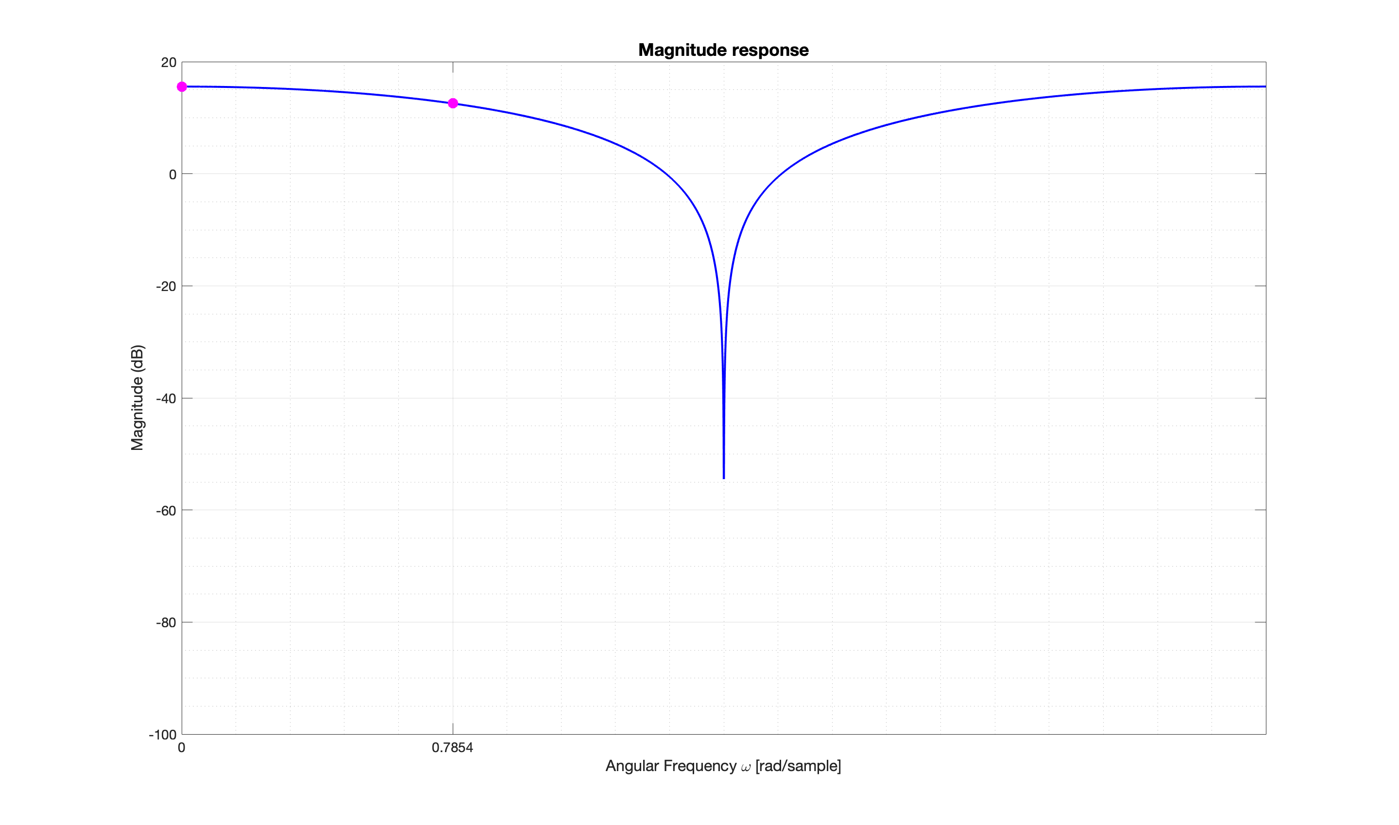
Giving you the flexibility to specify at whatever angular frequencies $\omega$ (in example above the evaluation is at two frequencies $0$ and $\pi/4$ rad/samples) you would want to evaluate the frequency response, (Here we're interested in the value at $\omega = 0$). The magnitude response with these two points is shown below
enter image description here

Note that the two points in magenta correspond exactly to

>> 20*log10(abs(h))

ans =

  15.563025007672874  12.552725051033063

>> 

The values at $\omega = 0$ and $\omega = \pi/4$ respectively.

$\endgroup$
5
  • 1
    $\begingroup$ Thank you, I understand! $\endgroup$
    – Mag
    Commented Dec 27, 2020 at 10:32
  • $\begingroup$ @user54828, you're welcome :). You can also upvote the answer (up arrow) if you found it useful. $\endgroup$
    – Gilles
    Commented Dec 27, 2020 at 10:37
  • $\begingroup$ my understanding though was that the frequency response would be defined as the DFT and thereby $H[k]=\sum_{n=0}^{N-1}h[n]e^{-j(2\pi /N)kn}$? Would you mind explaining why $e^{-j2\pi nF}$ works? $\endgroup$
    – Mag
    Commented Dec 27, 2020 at 15:59
  • 1
    $\begingroup$ @Mag , please see my edits and the new section From DTFT to DFT. $\endgroup$
    – Gilles
    Commented Dec 27, 2020 at 23:08
  • $\begingroup$ @Mag. Your H[k] equation is the most common (typical) version of the DFT equation. Gilles' DFT expression is non-standard in that his 'F' variable is a "relative frequency", where F = k/N, that is always less than one. $\endgroup$ Commented Dec 28, 2020 at 11:24
1
$\begingroup$

Giles' answer applies to tapped delay-line digital filters. A more general answer is: The DC gain of a digital system is the sum of the system's impulse response.

$\endgroup$

Your Answer

By clicking “Post Your Answer”, you agree to our terms of service and acknowledge you have read our privacy policy.

Not the answer you're looking for? Browse other questions tagged or ask your own question.