5
$\begingroup$

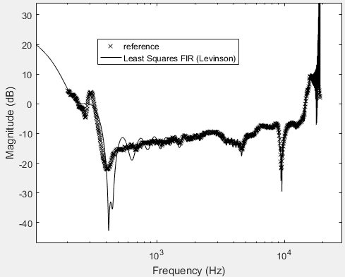
I'm using Matt. L.'s lslevin.m function to design long ($N\approx 400$) filters to an arbitrary phase and magnitude specification. The specification is the result of a numeric optimization and does cover frequencies between 200Hz and 19kHz. I found that the designed filters show poor approximation of my desired frequency response $H_1[k]$:

enter image description here

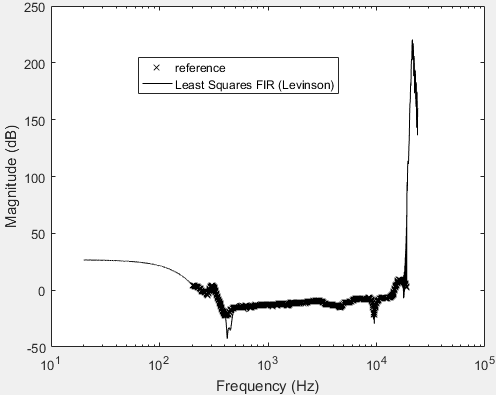
Apparently my desired response it hard to meet. Making the filters longer only amplifies the ripple. So I added a linear phase term $H_2[k] = H_1[k]e^{-j\frac{N-1}{2}\omega[k]}$ in the hope to make the desired response a little more realistic to meet. I am not sure why this is requried or why it makes things better, but it appears to be doing something. (Adding a (predictable) phase term to my filters is okay in my scenario as long as two filters designed with the same length have the same phase term added) Here's the result:

enter image description here

However, outside the range of specified frequencies I see huge spikes in the magnitude response (which is to be expected, because I don't control those regions at all):

enter image description here

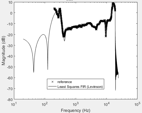
So I extended my specification by padding $H_2[k]$ with zeros on both sides. I give a weight of 2 to all points inside my specification and a weight of 1 to all the padded zeros - my hope is that I will get a band-pass behaviour with my desired phase and magnitude response in the passband and some sort of suppression outside the passband. I don#t really care about those regions but the huge magnitude from the previous example makes the impulse response have very large coefficients with varying sign which is impossible to implement. With the padding added, things start to look better.

enter image description here

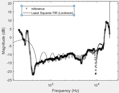
As you can (maybe) see, there is some ripple above 19kHz but in this case it stays low. If I increase the filter length $N$ to 600 or more - hoping to increase the accuracy of LS approximation in the passband - those ripples become extremely large, with the maxima reaching up to +50dB. Which makes this filter impossible to implement.

So as you can tell, I'm not entirely sure what I'm doing. How can I find a gradient of the linear phase term that yields the best approximation? How can I prevent huge magnitudes outside my important region of 200Hz-19kHz?

$\endgroup$
4
  • $\begingroup$ What's your sampling frequency? What does the desired phase response look like, and how important is it compared to the magnitude? $\endgroup$
    – Matt L.
    Commented Nov 13, 2018 at 17:57
  • $\begingroup$ @Matt L.: $F_s$ is 48kHz. The phase response is a wild mess. I would need to do the optimization on a extremely fine grid in order to be able to unwrap it properly. Phase response and magnitude response are equally important. The filtered signals will be played on loudspeakers so that the resulting sound field meets specific requirements. This is done by optimizing magnitudes and phases numerically to produce cancellation and amplification in certain points in space. That's why the only important aspect of the phase response is the phase difference between the output signals of my filters. $\endgroup$ Commented Nov 14, 2018 at 8:26
  • $\begingroup$ As only the relative phases between different filters really matter, I could in theory alter the responses for all my filters $H_i$ like this: $H_{i,new}[k] = H_i[k] e^{j\phi[k]}$ where $\phi[k]$ could be anything. If I had a way to tell how "close" my specification is to a causal (probably even linear phase) response, I could alter $\phi[k]$ to make the spec easier to meet. I would need an error function of some sort so I can optimize $\phi[k]$ but I have to idea what that error function could be. $\endgroup$ Commented Nov 14, 2018 at 8:30
  • $\begingroup$ If you like you can upload the magnitude and phase spec of that example in your question and I can see what I would come up with. $\endgroup$
    – Matt L.
    Commented Nov 14, 2018 at 11:13

2 Answers 2

2
$\begingroup$

In general you seem to be doing all the right things.

The linear phase term is required since an arbitrary magnitude and phase response is typically non-causal. That means it's impossible to fit with a causal filter and your fitting error is very high.

One way to estimate a "good" delay value is to sample your target on an FFT grid that's relatively dense and do an inverse FFT. Ideally this looks like an actual impulse response with a clear peak someplace and trailing off at the edge. Circulate this until you've captured the bulk of the energy.

The other options is to try brute force: just try a lot of delays and pick the one that gives you the smallest error.

Controlling the out of band behavior you can play around with the weights of the "don't care" bands. It's probably best to reduce the weights until the out of band energy is just about the same as the in-band energy. If you want real bandpass behavior, just apply a regular bandpass on top of your least square design. Trying to get a decent high pass at 250 Hz will cost you a lot of coefficients otherwise.

Your target has a lot of detail at low frequencies which determines the minimum number of FIR coefficients. You could try to prefit the major low frequency wiggles with an IIR filter and then just use an FIR for the remaining difference to the target.

$\endgroup$
1
  • $\begingroup$ Thank you, that was very helpful. I was expecting non-causality in my specification, but I never found a way to capture how non-causal it really is, without brute-forcing a solution with a fine-grid IFFT or just trying out various compensation terms. There must be a way to (perhaps numerically) calculate the compensation required. Right now, all I can do is eye-ball a solution, which seems extremely unelegant. $\endgroup$ Commented Nov 14, 2018 at 8:25
2
$\begingroup$

The approximation will be best if the average delay is close to half the filter length. However, optimizing the exact value of delay that has to be added to a given desired phase response is a highly non-linear problem, and you will end up in some local minimum. So the best approach is to simply search for the best delay. As soon as you've found it for a given filter length, then you also know it (at least approximately) for a new filter length (you simply add half the difference between the filter lengths to the delay that you've found).

I do not understand yet why you get large ripples for longer filters after having specified the don't-care regions as stopbands with low weight. The filter should approximate the desired value of zero, also for large filter lengths, albeit with a larger error because of the low weight.

One more thing you should try to do is introduce transition regions (i.e., regions without any specs) between the specified band and the stopbands close to DC and close to Nyquist. This will improve the approximation in the band where the response is specified, and it will also help avoid undesirable behavior in the don't-care bands. The width of these transition bands depends on the filter length. If they are too narrow, the don't help much, and if they are too wide, the filter will have large magnitude peaks in those bands. So this is again a matter of trial and error.

$\endgroup$

Your Answer

By clicking “Post Your Answer”, you agree to our terms of service and acknowledge you have read our privacy policy.

Not the answer you're looking for? Browse other questions tagged or ask your own question.