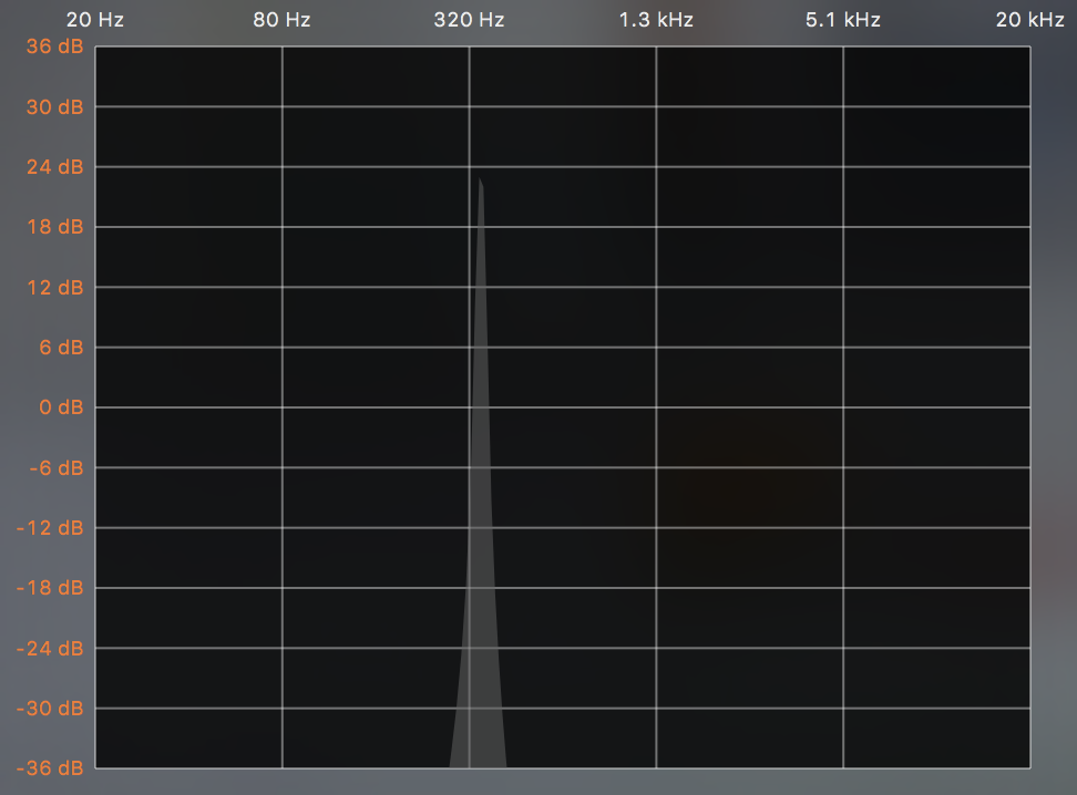
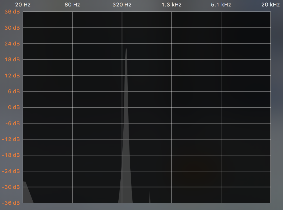
This is likely due to a truncation of your sine wave in the time interval you have chosen, such that there is not an integer multiple number of sine wave cycles chosen. I am guessing that your frequency view that you provide above is a subsequent measurement (DFT) from the resulting time domain waveform you have created, and not a view of your original frequency function you are using to create the time domain waveform (as the original function in the frequency domain would not have those artifacts!).
That said, the specific answer will depend on how exactly you create and repeat/extend the final time domain waveform from the fixed length IFFT result that you get, but below are some insights on the effects of waveform truncation in the time domain that may help you to understand how you may be getting such artifacts.
A direct and concise mathematical answer of frequency effects from waveform truncation can be derived by describing your fixed length (sampled) waveform in the time domain as an infinite length waveform multiplied that is not truncated by a rectangular (boxcar) window. Multiplication in the time domain is convolution in the frequency domain, so the result of a boxcar window truncation would be convolving the frequency you would get without truncation with a sinc function (or when sampled, the approximation of a sinc function).
I like to view the resulting effect by picturing the time domain waveform extending from minus infinity to positive infinity in time, made up of your specific waveform snippet (IFFT result) continuously repeating in time. For a direct DFT this analogy this is mathematically valid (meaning the DFT over the finite time interval would match the DTFT of the same sequence repeating it time (just that the DTFT would be a continuous function and the DFT would be samples of this function- see below). Repetition in the time domain over an interval T results in a FT with discrete impulses in the frequency domain spaced at 1/T.).
From this view it may be clearer to see the effects of truncation: if we had 1.5 cycles of a sine wave in your time interval, the sine wave would suddenly snap every 1.5 cycles in the repeating waveform, requiring higher frequencies to achieve this "snap" that takes place in time. In contrast if you had an exact integer number of cycles (for a samples system, samples 0 to N-1, where sample 0 would be identical to the sample N for a pure undistorted sine wave), then the FT result (and DFT and DTFT) would only exist at one frequency location with 0 elsewhere; as expected for a pure tone.
FT, DTFT, DFT Background
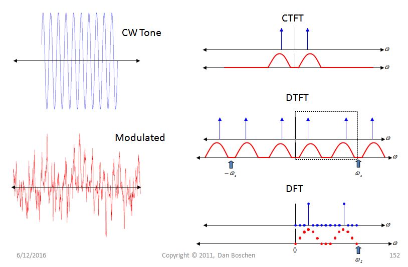
I reference FT, DTFT, and DFT above, so I included this graphic and primer below to help clear up any confusion for those less familiar.

What is shown is the FT (or CTFT), DTFT, and DFT for a pure tone (that in "truth" extends from minus infinity to infinity in time), along with a modulated waveform of finite bandwidth. In the Fourier Transforms, the tone is shown in blue while the modulated waveform is shown in red, and $\omega_s$ is the sampling frequency.
The CTFT is the Continuous Time Fourier Transform, or Fourier Transform (FT) for short.
$$ X(\omega) = \int_{t=-\infty}^\infty x(t)e^{-j\omega t}dt $$
Observe:
continuous in time -> aperiodic in frequency
aperiodic in time -> continuous in frequency
The DTFT is the Discrete Time Fourier Transform; the time interval still goes from minus infinity to infinity, but the system is now sampled. It is a sampled FT, which create repetition in frequency.
$$ X(\omega) = \sum_{n=-\infty}^\infty x[n]e^{-j\omega n} $$
Observe:
discrete in time -> periodic in frequency
aperiodic in time -> continuous in frequency
The DFT is the Discrete Fourier Transform; the time interval is defined over a finite interval. There is an implied periodicity in time, meaning if you made a waveform by repeating this one in time from minus infinity to infinity, the DTFT of this periodic waveform would match the DFT at the DFT sample locations (see plot above).
$$ X[k] = \sum_{n=0}^{N-1}x[n] e^{-j\omega_o k/n} $$
Observe:
discrete in time -> periodic in frequency (implied)
periodic in time (implied) -> discrete in frequency
*note the time domain and frequency domain waveforms are not really periodic, as they only exist over a finite number of samples- but I like to make this interpretation, as if you did repeat the waveform in both domains you would get the same valued discrete samples (but they would be continuous waveforms with zero values in between). This interpretation has been extremely helpful for me in working with mixed signal (analog/digital) systems.


