0
$\begingroup$

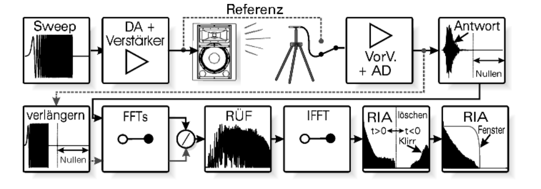
I am currently working on my master thesis and have so far generated a broadband ESS to obtain frequency response and impulse response. To generate the ESS as an excitation signal I use the following formula:

𝑥(𝑡)=sin(2𝜋𝑓1𝑇𝑅(𝑒𝑡𝑅𝑇-1)).

See: Calculating the inverse filter for the (exponential) sine sweep Method

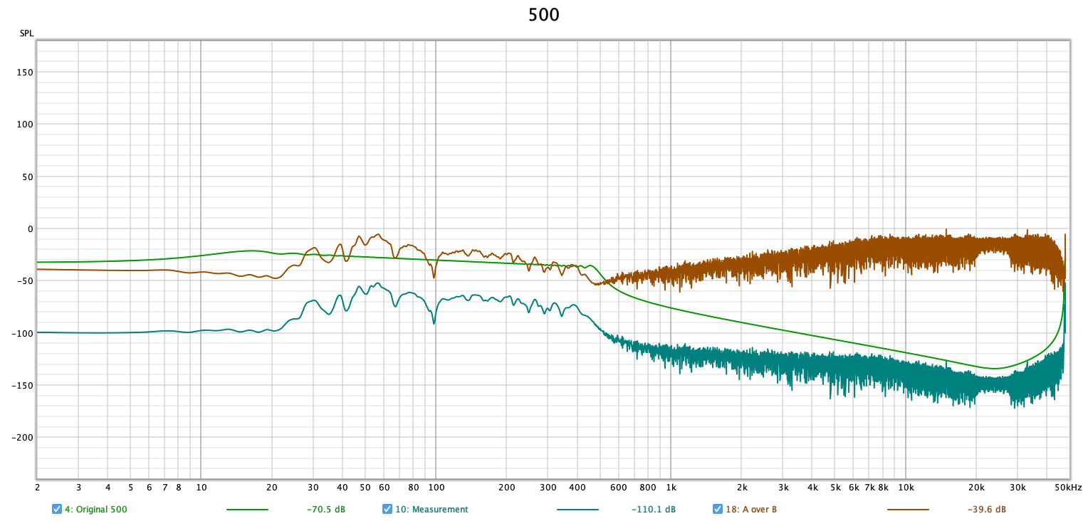
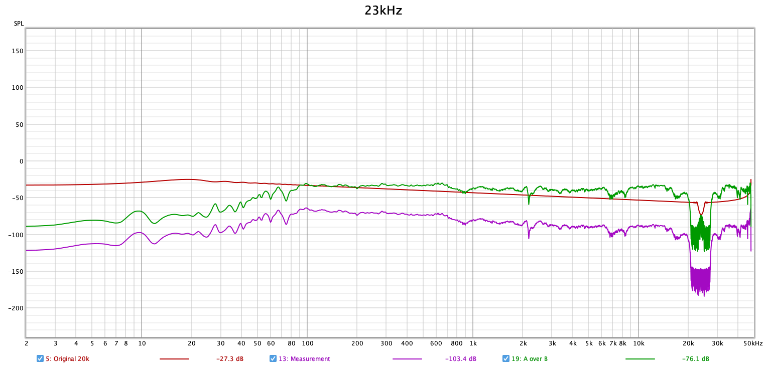
For the broadband signal, I chose f1=10Hz and f2=23kHz. After recording the excitation signal, I get my spectrum via complex division and with subsequent IFFT my impulse response. enter image description here
Here everything still works great (see picture ESS20k). But for my subwoofer I want to create an excitation signal with f2=500. But there are errors in the spectrum, as well as in the impulse response(See picture ESS500Fehler).

enter image description here enter image description here

enter image description here

I know that it has something to do with the frequency spectrum above 500Hz. If I set this above 500Hz to -150dB, I at least get a recognizable impulse response. However, this leads to problems as soon as you move the measurement window (I have done this so far to measure the distance). If anyone could help me even with a new way of thinking, I would be very grateful.

$\endgroup$
1
  • $\begingroup$ You can find information on the ESS here (very nice answer) and here (kinda more generic). All in all, most probably, the problem here is related to numerical errors due to very small values in the spectrum of your sub-woofer response. Thus, the inversion/deconvolution gives erroneous results. The best solution I am aware of is to calculate the inverse filter in the time domain. $\endgroup$
    – ZaellixA
    Commented Sep 16, 2023 at 14:55

1 Answer 1

3
$\begingroup$

That's a typical problem with sweep measurements and complex division. You often have some amount of noise in your measurement, so your acquired signal,yy, becomes

$$y[n] = x[n]*h[n]+q[n]$$

where x is your excitation, h the impulse response and q some additive noise. With spectral division your transfer function estimate becomes

$$H_{est}[k] = \frac{Y[k]}{X[k]} = H[k]+\frac{Q[k]}{X[k]}$$

That means your noise spectrum is amplified by the inverse of the excitation sine. For a limited range sweep the energy outside the sweep-range is very low, so you get a lot of noise amplification. Since the inverse DFT requires information at ALL frequencies, that amplified noise messes up your impulse response.

One possible workaround would be to calculate the impulse response in the time domain using an LMS or least squared algorithm. You can also try inverting the excitation, band-pass filtering the inverted impulse response and than convolving with the acquisition.

Alternatively you can construct an excitation that has "sufficient" energy at all frequencies, i.e. $X[k] \gg Q[k]$. That can be done with sweeps but it's tricky. It's much easier if you use a pseudo random noise where you can directly optimize the excitation spectrum based on your noise spectrum (which is typically brown or pink) and your requirements. This as also the added benefit that pseudo random noise reacts more benign to non-linear distortions. Sweeps are sensitive to the 2nd and 3rd order distortions of a typical electromagnetic driver: the noise energy tends to concentrate in time so you can end up with "ghost reflections".

$\endgroup$
1
  • $\begingroup$ What a relief. Thanks for the quick reply, both Hilmar and @ZaellixA helped me a lot. I have now formed the inverse impulse response and multiplied it with the measurement signal complex. This was the best result. $\endgroup$ Commented Sep 18, 2023 at 14:47

Your Answer

By clicking “Post Your Answer”, you agree to our terms of service and acknowledge you have read our privacy policy.

Not the answer you're looking for? Browse other questions tagged or ask your own question.