Your message was apparently unfinished ('When reading about the DCT...'). I thus will be starting from it.
The JPEG compression format is an example of hopping. A DCT-filter bank (Discrete Cosine Transform) is applied on the whole image, and subsampled by $8\times 8$ (in both directions). Another interpretation is via a rectangular window, implemented in a fake overlap-add version, as the overlap is zero ($8\times 8$ blocks are almost disjoint). The DCT has a very simple interpretation, as it consists of an infinite continuous cosine basis, discretized and windowed with a rectangular window.
The traditional Short Term Fourier Transform (STFT) is an improvement, with the use of an overlapping window. In the continuous setting, an STFT with a window $h$ can be inverted with a lot of dual windows $g$ (under very mild assumptions on $h$ and $g$).
Going to discrete implementations, certain choices of overlap, hop and window can lead to easy inversion. Inversion, or synthesis is the turning point: you can "analyse" any signal with any window, or hop. But not all designs allow synthesis or inversion, although it should be permitted more easily than in the critical and orthogonal framework, because of the potential redundancy.
There are instance of windows allowing discrete, non-redundant inversion, like the Modified DCT, the LOT (lapped orthogonal transform), the MLT (modulated lapped transform), and a handful of others (GenLOT, GULLOT). They are used for instance in the mp3 (mpeg-1 layer 3) style of audio compression.
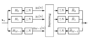
In the above case, the hop is equal to the number of channels, similarly to the case of the JPEG DCT: $8$-channel DCT, and a jump of $8$ pixels in each direction. Allowing only a window for all the channels is somewhat restrictive. The most efficient framework is that of oversampled filter banks:

There is no direct concept of a global window for all $M$-band filters, $M\ge N$. Instead, some windowing is embedded in each one. In the above picture, the $N$ corresponds to your $R$. My understanding is that the downsampling takes place in the time-domain (hopping), but it results in a shift in frequency (and aliasing), as filter $H_i$ outputs are sent to the base-band.
Then, given a set of analysis filters $H_i$ (including some overlapping), and if $M$ is greater than $N$, you can very often cancel all the aliasing induced by the $N$ downsampling with an infinity of inverse filter banks. One issue is to find ONE suitable inverse.
This is discussed for instance in Optimization of Synthesis Oversampled Complex Filter Banks, J. Gauthier et al., IEEE Transactions on Signal Processing, 2009:
An important issue with oversampled FIR analysis filter banks (FBs) is
to determine inverse synthesis FBs, when they exist. Given any complex
oversampled FIR analysis FB, we first provide an algorithm to
determine whether there exists an inverse FIR synthesis system. We
also provide a method to ensure the Hermitian symmetry property on the
synthesis side, which is serviceable to processing real-valued
signals. As an invertible analysis scheme corresponds to a redundant
decomposition, there is no unique inverse FB. Given a particular
solution, we parameterize the whole family of inverses through a null
space projection. The resulting reduced parameter set simplifies
design procedures, since the perfect reconstruction constrained
optimization problem is recast as an unconstrained optimization
problem. The design of optimized synthesis FBs based on time or
frequency localization criteria is then investigated, using a simple
yet efficient gradient algorithm.

