2
$\begingroup$

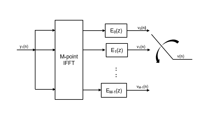
I am referring to the Xilinx application note Polyphase Filter Bank Channelizer. The receiver portion should have FFT but the pdf mentions IFFT in both Tx and Rx.

The paper by F. J. Harris, C. Dick and M. Rice, "Digital receivers and transmitters using polyphase filter banks for wireless communications," in IEEE Transactions on Microwave Theory and Techniques, vol. 51, no. 4, pp. 1395-1412, April 2003 also mentions the same.

How did Xilinx get proper results by implementing IFFT in both Tx and Rx?

$\endgroup$

3 Answers 3

3
$\begingroup$

Forward DFT and Inverse DFT are quite similar transforms related by the following:

Let $x[n]$ be a length $N$ sequence, $X_f[k]$ be its N-point forward DFT, and $x_i[k]$ be its N-point inverse DFT : (ignore whatever that $k$ or $n$ refers to, let it be just a sequence index.)

$$X_f[k] = \text{DFT}\{x[n]\} = \sum_{n=0}^{N-1} x[n] e^{-j\frac{2\pi}{N}nk}$$ $$x_i[k] = \text{I-DFT}\{x[n]\} = \frac{1}{N}\sum_{n=0}^{N-1} x[n] e^{j\frac{2\pi}{N}nk}$$

Then $X_f[k]$ and $x_i[k]$ are related by:

$$ X_f[k] = N ~ x_i[-k] $$

where $x_i[-k]$ is the circularly reversed sequence $x_i[k]$.

As you can see, the forward and inverse DFT results are (almost) identical except a linear scale by $N$ and reversed ouput ordering. Hence, you can use either of them to compute the other, by performing the scaling and re-ordering properly.

$\endgroup$
1
$\begingroup$

Sorry, I didn't read the paper so this is just a guess.

FFT and IFFT are almost identical algorithms so it really makes no sense to code up both in an FPGA. Just use

$$F^{-1} (x) = F(x')/N, \\ F(x) = N \cdot F^{-1}(x)'$$

where N is the length of the FFT and "'" to conjugate complex operator.

$\endgroup$
1
$\begingroup$

To start with, XAPP1161's developers re-use, for their transmitter and receiver blocks, the objects dsp.ChannelSynthesis and dsp.Channelizer, respectively. These are objects of MATLAB's DSP System Toolbox. The Channel Synthesizer block diagram corresponds to the transmitter block in XAPP1161's Figure 3 Polyphase Filter Bank (page 3),

enter image description here

and the Channelizer block diagram corresponds to the receiver block in XAPP1161's Figure 3 Polyphase Filter Bank (page 3) with the only exception: XAPP1161 shows M-point IFFT at its output to an $y(m)$ bus, while the MATLAB block that outputs an $y(m)$ bus is M-point FFT.

enter image description here

This "discrepancy" (rather, typo) does not affect the operation of the XILINX demo solution, because the design files use "right" objects of MATLAB's DSP System Toolbox, dsp.ChannelSynthesis and dsp.Channelizer, and not what the texts the developers inscribed into their drawings indicate.

Harris/Dick/Rice's paper also uses IFFT in transmitter and FFT in receiver blocks, respectively (Figure 27, page 13):

Rice's paper, Figure 27 (page 13)

$\endgroup$
0

Your Answer

By clicking “Post Your Answer”, you agree to our terms of service and acknowledge you have read our privacy policy.

Not the answer you're looking for? Browse other questions tagged or ask your own question.