4
$\begingroup$

I am struggling with understanding the consequences of oversampling on the frequency spectrum of the signal.

If I understand correctly, with an oversampling rate of 8X we insert 7 new values for each value measured. In case we keep this new values at 0 then we are not inserting any new frequencies to the signal, so the frequency spectrum should stay the same.

On the other hand, if we interpolate the new values eg by averaging the adjacent ones, then we MIGHT generate some new frequencies, that might appear in our frequency spectrum. This new inserted freuquencies will be of higher magnitude and should be filtered out if we want to keep the signal as "clean" as possible.

Am I correct with my understanding of oversampling and interpolation? Thanks in advance for any answer!

$\endgroup$
2
  • 4
    $\begingroup$ Inserting zeros between samples has the effect of replicating the signal's spectrum. Thus, one would apply a low-pass filter to this zero-interleaved data to remove these copies and complete the upsampling. $\endgroup$ Commented Jan 23, 2020 at 18:05
  • $\begingroup$ Related $\endgroup$ Commented Nov 1, 2020 at 16:06

5 Answers 5

5
$\begingroup$

The key to understanding what inserting zeros does is to understand two things: what samples represent in the time domain (because we want to insert zeros in the time domain), and what they represent in the frequency domain (because we want to know what it did to the spectrum).

First, sampling is a type of modulation (PAM—Pulse Amplitude Modulation), equivalent to multiplying an impulse train by our analog signal, and creates images in the frequency domain. When converted to digital sample values, we have PCM (Pulse Code Modulation), a common term for digital audio. Here is an example spectrum represented by our samples; the original analog signal's spectrum is shown in green, and images in red:

Original spectrum These images are the price we pay to represent the analog signal as samples. As such, the usable bandwidth is from 0 Hz up to (but not including) half the sample rate. Above that is a backwards image of our original spectrum, with images repeated around multiples of the sample rate. It's OK, we remove the images when we convert back to analog, using a DAC's lowpass filter.

In the time domain, samples represent impulses. They are instantaneous values taken at a constant interval. Inserting zeros changes nothing except what we consider the sample rate.

For instance, sample a signal one time per second. That represents an impulse train, so consider playing it back raw, as an impulse train.

Now consider placing a zero-valued sample between each of the original samples. Consider playing it back as an impulse train but at twice the original rate, two times per second.

Zero insertion

Can you see that nothing has changed in the signal, except the sample rate? Likewise, if we look at the spectrum, nothing has changed in the frequency domain—this is obvious, since the time domain signal has not changed.

Upsampled spectrum

However, our usable bandwidth has doubled. The first inverted image now lies in our usable band, now shown in green. It will not be removed by the DAC when played back through a DAC at the new, higher rate. And it will be a problem with any non-linear processing in the digital domain.

That is why we follow the zero-insertion with a lowpass filter (or combine the two steps for efficiency). Here it is again after proper filtering, below half the original sample rate:

Upsampled and filtered spectrum

So, the answer is that nothing changes in proper integer sample rate conversion by zero-insertion, and the result is as perfect as the lowpass filter used to clean up the exposed images.

$\endgroup$
0
3
$\begingroup$

Yes inserting zeros does insert new frequencies in the unique digital spectrum that extends from $0$ to $2\pi$ radians/sample or equivalently $\pm \pi$ radians/sample corresponding to $\pm F_s/2$ where $F_s$ is the sampling rate. The easiest way to see this intuitively is to consider a DC signal represented by a stream of constants, such as:

$x_1 = \begin{bmatrix}1 & 1 & 1 & 1 &1 ...\end{bmatrix}$

This is clearly a sampled DC signal, but insert zeros and we get:

$x_2 = \begin{bmatrix}1 & 0 & 0 & 0 & 1 & 0 & 0 & 0 & 1 & 0 & 0 & 0 & 1 & 0 & 0 & 0 &1 ...\end{bmatrix}$

Now we have a series of periodic impulses (unit samples).

Consider the same in the continuous time domain if that is easier to see: The Fourier Transform for a series of repeat impulses in the time domain is a series of repeated impulses in the Frequency domain. Each harmonic will be a multiple of the repetition rate (which makes sense).

In short, changing the time response of the signal requires non-zero frequency content. We started with DC so the frequency content was a tone at frequency = 0. If we then make that constant value in time abruptly change in one single sample all the way to zero; such a relatively fast change would require very high frequencies. If we instead changes slowly toward zero over many samples, the frequency content would dominate in lower frequencies (slow change).

Further when we are strictly in the digital domain inserting a zero is NOT the same as the empty undefined space between samples. The periodic spectrum when extended beyond the sampling rate prior to inserting zeros, does become the new spectrum with the zeros inserted, as I explain further in the linked posts that provide a more theoretical insight. However this is indeed a change and with that can certainly be described as a creation of new signals in our digital spectrum from the point of consideration that our unique digital spectrum of interest extends from $0$ to $2\pi$ radians/sample. I can understand from this philosophically how one can say "No new frequencies are inserted" since the periodic spectrum that exists is simply compressed on our frequency axis. Personally, when I am working in the digital domain, I typically normalize the sampling rate to $1$ cycle/sample or $2\pi$ radians/sample and view it from that perspective until actually having to translate to/from the analog world. So if I do a process in the digital domain that changes the spectrum in that range such as zero inserts- I would describe that as inserting new frequencies.

For further details on that and applying this to interpolation see:

Fourier Transform of an Impulse Train

Higher order harmonics during sampling

Interpolation through zero insert and filtering:

Choosing right cut-off frequency for a LP filter in upsampler

What is the impulse response used in an interpolation filter when upsampling?

Ideal Interpolation Filter for zero insert resampling:

Downsample: resample vs antialias fitlering + decimation

$\endgroup$
10
  • $\begingroup$ The problem here is that you're considering the first example as representing a DC value and nothing else, while the second you're considering as having repeated frequency content. However, the first signal is sampled and therefore also has repeated frequency content. In fact, it's exactly the sample frequency content as the second, assume the first represents a 1x sample rate and the second 4x. That is, if you play back the first, without filtering, and the second at 4x that rate, both will look the same in both time and frequency domains. $\endgroup$ Commented Jan 24, 2020 at 0:02
  • $\begingroup$ @earlevel Yes agreed but in that context I am only referring to the first Nyquist zone- the unique digital frequency span from 0 to $F_s$ and for that this all applies. $\endgroup$ Commented Jan 24, 2020 at 0:15
  • $\begingroup$ Think it it this way, all ones is the sampled representation of a DC signal. Insert zeros and you will have additional frequencies within your normalized frequency span between 0 and $F_s$. In the links I explain the points you are also making but this is an intuitive way to look at it that is completely valid. $\endgroup$ Commented Jan 24, 2020 at 0:20
  • $\begingroup$ Yes, I understand the point of view, since frequencies (that were there in the first place) are now in the band of interest (because it has been widened. I did want to comment on it, though, because it conflicts with my answer here, if you boil both of our answer down ("yes it does" vs "no it doesn't" posts of view). $\endgroup$ Commented Jan 24, 2020 at 0:52
  • $\begingroup$ Ah i see your reason to comment - yes important to clarify what one means by “new frequencies” and then almost gets philosophical. Both good answers I think and helpful. $\endgroup$ Commented Jan 24, 2020 at 0:57
1
$\begingroup$

Interpolation by avaraging does introduce new frequencies as it doesn't reproduce the signal assumed to be the original one. The correct way to interpolate the new values is the Shannon interpolation. Ps: This method is equally correct in the time and frequency domains.

$\endgroup$
1
$\begingroup$

What you define as oversampling is actually sequence expansion by zero stuffing in between its samples. Which is an operation performed as a prerequisite of interpolation. And yes; zero stuffing a sequence will alter its spectrum as explained by DanBoschen.

Oversampling implies an ADC operation in which a signal is sampled above its Nyquist rate. This operation does not alter the frequency spectrum of the signal but it effects the amplitude scaling of it. Furthermore in an oversampled signal the spectrum will be zero after the signal bandwidth up to the Nyquist frequency.

Note that consequence of oversampling in the discrete-time frequency is that, the frequency axis is compressed from the frequency $\omega = \pi$ towards $\omega = 0$; so this is also a change in relative positioning of frequencies. (But which can be reverted.)

$\endgroup$
0
$\begingroup$

Zero stuffing does not insert additional frequencies and the frequencies above the original signal frequency are not present in the original signal; however, because the signal is a set of samples, there are convolved images in the frequency domain, and the upper half of the frequencies in the new nyquist frequency range of the sampler that is 2x the size of the original will be taken up by the first duplicate (image), so unwanted frequencies will be in the sample. It simply increases the amount of frequencies that are sampled, i.e. the period of sampling in the frequency domain widens and ends up including the next image of the original signal in the frequency domain, which is known as imaging.
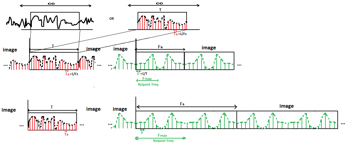
enter image description here

The original signal is by definition an aperiodic signal. It is either a continuous symbol of finite duration sent over the air (row 1, left) that gets sampled within a sampling window of the same size (or reduced size if using CPs or windowing) at a certain sampling frequency that is expected at the source and standardised, or we are talking about samples in an audio file on a disk (row 1, right), and the latter case is the only time you see upsampling. In both cases, they are finite, so it is aperiodic regardless of whether there is any kind of period within that signal. The first and final sample in the file acts as a rect window, making it aperiodic. For a symbol, it is physically windowed (truncated) when it is sent and the sampling window at the receiver also acts as a truncation of the symbol, and then the time domain samples are samples of that truncation (meaning the frequency domain samples sample sincs).

The result of sampling the time domain (multiplying by Dirac comb) is a repeating, continuous frequency domain, where the dual lobes around the 0 frequency axis repeat at intervals of the nyquist rate Fs.

Ultimately, you have an aperiodic discrete set of time domain samples (row 2, left), and as the frequency domain is produced using the DFT, you end up with samples of the repeating frequency domain that would have been continuous, which then results in infinite repetition (images) in the time domain – when working with frequency samples, the time domain has infinitely repeating images outside of the sampling window that mathematically replace everything surrounding it that wasn't captured and sampled. The presence of samples in one domain makes the other repeat, and the presence of samples (and hence the images also being samples, because it's the only set of discrete frequencies that can be acquired from it through the actual samples) is brought about by DFT. Therefore you end up discrete samples in both domains through the DFT, where there is implicit repetition, such that when you use a discrete frequency in the image that does not belong to one of the samples, it will alias to one of the samples.

The sampling window Fs will need to be set to twice the size of the maximum frequency component, Fmax of the signal when sampling it in order to capture that range of frequencies without them ending up being aliases of other frequencies within the range of Fmax. It needs to be sampled at at least Fs as the Nyquist rate, which is the maximum frequency component in the signal x2. When this time domain signal is sampled every Ts seconds, it convolves the frequency domain every Fs.

On the 3rd row, we upsample a time domain signal 2x which is already a set of samples and hence already has infinite images in the frequency domain. Because it is multiplying a set of impulses with a denser set of impulses, there will be 0s where the impulses don't intersect (the dotted line shows the envelope of the impulses and not a continuous signal, so it is actually 0 between the impulses; these zero samples are shown as red dots on the line) (in this case every other sample will be a 0 because we are upsampling 2x. Ts is now half the Ts of the original signal). The frequency domain of the signal will now be convolved every 2Fs. The new Fs is 2x the original. The time domain samples will just be the original samples but with 0s interspersed between the original samples.

The resulting frequency domain is identical, except Fs now covers a 2x larger window of the frequency domain. This means that you need a low pass filter at the maximum frequency of the original signal to remove the unwanted frequencies from the nyquist frequency range to get the same identical components within the nyquist range you would have got from sampling the original continuous signal at that 2x sampling rate. This can be done in the digital domain by making those frequency samples 0 and performing an IDFT as opposed to using an anti-aliasing filter before an ADC, but of course zeroing in the digital frequency domain will never manifest perfectly when it reenters the analogue domain because the reconstruction filter at the DAC will always have a rolloff similar to the anti-aliasing filter, except in this case, the reconstruction filter is at the higher sampling frequency where there is a large gap between it and the Fmax of the original signal, which is why we upsample audio.

Anti-aliasing filters prevents frequencies outside the sampling frequency from aliasing with the frequencies that are sampled when the actual sample is taken at the ADC, and the reconstruction filter at a DAC removes the new images that appears in the digital domain by virtue of being a set of time and frequency domain samples.

Sampling the original time domain signal 2x would have yielded:
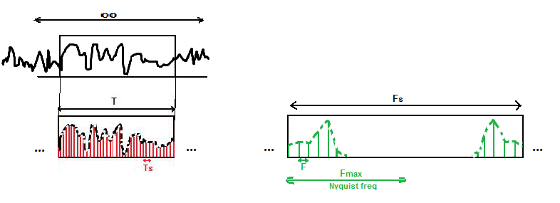
enter image description here

You don't need a low pass filter here because the images are greater than the Nyquist frequency (they fall outside of Fs), and there's nothing to low pass filter out because there are no images from the smaller Fs of the 1/2 sampling rate within the new nyquist frequency.

When you filter out the imaging of the upsample in the first scenario, the frequency domain resembles the above scenario. It is called interpolation, because it turns each 0 into an interpolation between the points either side, to match identically the time domain of above scenario. The zero stuffing is the prerequisite part of interpolation.

All in all, upsampling is the process of zero stuffing and interpolating (filtering) a set of samples of signal to give the set of samples a higher sampling rate, as if they had been taken from the original analogue signal at that higher sampling rate. The underlying frequency components in the signal does not change. You are just sampling it at a higher rate.

The DFT of the zero stuffed time domain samples on row 3 (as opposed to the x2 samples of the signal) is the original frequency domain samples and another set of samples with the same cardinality concatenated to the end. If you make the centre samples 0 (the samples with a frequency alias absolute value within Fs) and perform an IDFT, the samples in the resulting set of time domain samples that were previously 0 now become interpolated points. If you instead made the latter half of the samples 0, you'd get complex time domain samples because you wouldn't have an odd or an even function within the sampling window.

The frequency domain is a series of infinite images which has been multiplied by the filter and convolved with the window, which is why the rolloff of the filter matters, because the filter is not being multiplied by 0, but by images (and the side lobes of the frequency domain sinc impulses). It is a series of infinite images because the time domain was a series of impulses, which were windowed to the signal length (which merely causes a convolution around the impulses in the images) and then the multiplication with the filter removes all of these images and the most possible of the 2 immediately adjacent images either side.

The original signal and the upsampled signal have the same window size and therefore the impulses representing the samples in the frequency domain have the same shape and size. The impulses in the time domain of the upsampled signal are 2x closer together, hence the ZOH DAC frequency response and resulting pulse shape filter frequency response (that gets multiplied with the frequency domain due to its convolution in the time domain) is wider to match the increased number of frequencies. The pulse shape filter has rolloff in both cases (and in the 2x original sampling case), because the sinc time domain pulse shape that is used to reconstruct cannot be infinite, because the signal is finite, and therefore it is not a perfect rect shape brick wall filter in the frequency domain. The anti-aliasing low pass filter at the receiver before the ADC that is convolved with the time domain also has a rolloff in the frequency domain.

The point of upsampling is to move the reconstruction/anti-aliasing filter well above audible frequencies, where it can be more gentle and not affect the audible spectrum. A high-quality filter at 22khz is hard to make in hardware without distorting phase and without cutting into frequencies below 20khz. A gentle filter at 88khz is much easier, and it can distort there all it wants without affecting the audible range. It's a simple engineering solution to a problem that could otherwise become audible... at least to some of us (not to me, not for a while) [1]

Basically, the right side of the rolloff occurs at a higher frequency on the upsampled signal and the left side of the rolloff is the same negative frequency in both cases which aliases to an even higher frequency than the left side. Because the right rolloff is now at a higher frequency, the effects of the aliases (images) that aren't completely removed by a DAC reconstruction filter (as it's not a brick wall) playing the audio are minimised because 1. those extra frequency components are at a frequency outside of the audible range and 2. the aliases that appear due to the rolloff (transition band) being greater than Fs/2 are much lower power because the side lobes of the sincs have dissipated even more by this point, because the gap between the original FMax and the rolloff is now 3*FMax rather than FMax.

$\endgroup$

Your Answer

By clicking “Post Your Answer”, you agree to our terms of service and acknowledge you have read our privacy policy.

Not the answer you're looking for? Browse other questions tagged or ask your own question.