Non technically speaking without coefficients and formulas, how do an audio filter cuts off low frequency from a sampled audio w.r.t cut-off frequency ?
-
$\begingroup$ Did you intend to describe a high pass filter (meaning pass high frequencies and attenuate low frequencies)? In that case my answer below does not apply and I will delete it. Sorry to confuse, please clarify first. $\endgroup$– Dan BoschenCommented Apr 7, 2017 at 2:25
3 Answers
But I really wanted to write coefficients and formulas! Oh well, ok...in simplest terms a low pass filter is a weighted moving average. Consider charts of stock market prices and look at the minute by minute pricing compared to a "30 day moving average" and ask yourself which plot contains higher frequencies?
By adjusting the weights of each delayed copy of our signal when we combine them in the process of determining the average, we can change the characteristics of the filter in how it attenuates versus frequency. So consider the filter as a moving window that we can average over (the memory of the filter) and higher frequency components that have many cycles within the window duration will tend to average out over this window length, while lower frequency components will not go fully plus and minus over the duration of our window so will not average out and will pass through.
For all filters analog and digital, to attenuate faster, more delay is necessary. It is amazing how much we can do from just delays and adds with weighting of each of those delayed outputs!
Update: It appears the OP is asking about a high pass filter, while the above description pertains to a low pass filter. Note that we can take a linear phase (constant delay) low pass filter and subtract it from a delayed and gain (DC gain) matched version of the input (matching the delay of the filter but passing all frequencies equally), we would achieve the desired high pass response. That may help to see how the same factors related to delay and filter performance apply. (This is not how I would typically implement a high pass filter as we can modify the coefficients directly, but gives insight into the process).
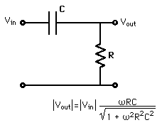
An electronic filter has components which their impedance are frequency dependent (Capacitors, Inductors). This gives a frequency response curve. As you alter frequency the gain of your filter changes. You place these components in your circuit to get a desired response. Usually you use an active component for gain (Op-Amp or transistor). The simplest example for a HPF in your question is an RC-filter (Capacitor in series with resistor, feed input signal into capacitor, take output across resistor).
Assumed definition of cutoff frequency: "frequency at which the signal drops by 3dB (amplitude drops by a factor of sqrt(2), power drops by a factor of 2)"
At the cutoff frequency the amplitude of the signal will 1/sqrt(2) times as large as it was before the high pass filter. Frequencies lower than the cutoff frequency suffer *greater attenuation depending on how far away they are from the cutoff frequency.
I put an "*" by the word "greater" because some filters will not roll off monotonically at all frequencies below cut-off. Check out this link to see what I mean:
https://www.mathworks.com/help/signal/examples/filter-design-gallery.html

