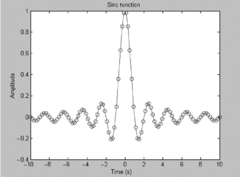
As it relates to linear filtering, the sinc function often comes up because it is impulse response of an ideal lowpass filter (i.e. one that has a perfectly flat passband and a transition region of zero width). In many applications, having such a filter response would be a great tool, as you could perfectly excise any out-of-band interference without disturbing a signal's passband at all.
However, there's a problem, as you noted in your question: $\text{sinc}(t)$ has infinite support! In other words, the impulse response of an ideal lowpass filter is infinitely long. That's not necessarily an issue (a lot of filters have infinitely-long impulse responses), but the big problem is that if the filter is causal (which it certainly must be in order to be realizable), then it will have infinite delay. So, if you were clever enough to build such a contraption, you would find that you would need to wait an infinite amount of time in order to see the filter's response for a given input signal. That tends to make such an idealized filter less useful in practice (even if you could build it).
With that said, while an ideal filter may not be practical, an approximation to an ideal filter can be. One simple way of designing filters, the window method, relies upon taking some filter prototype (an ideal lowpass filter, for instance) and multiplying its impulse response by a finite-length window function. The specific window function used will affect the properties of the resulting filter, but the typical goal is to approximate the prototype filter's response with something that is actually realizable. As a result, a windowed ideal lowpass filter will still have an impulse response that looks $\text{sinc}$-like over some finite-length interval. Since a causal filter's impulse response starts at $t=0$, the main lobe of the impulse response won't occur until some later time; this is what manifests itself as filter delay.
The plot that you showed is for $\text{sinc}(t)$, which is the ideal, noncausal ideal lowpass filter's impulse response. Translating that to an implementable approximation requires truncating its response to a finite length (i.e. through windowing it) and shifting its response along the time axis so that the filter is causal (after shifting, its response would begin at $t=0$ as you expect).

