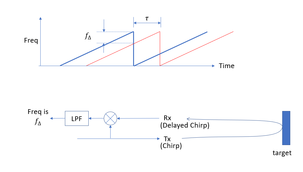
The range calculation for FMCW is much simpler than this and quite intuitive- since the chirp is “unchirped” in the receiver we can compute everything based on the received IF waveform as a frequency vs time, using the ramp rate of the chirp as a simple delay to frequency converter. From that we can estimate velocity to account for Doppler offsets for the case of moving targets.
First reviewing the basic FMCW ranging operation: Given a ramp rate in frequency and a stationary object, the round trip delay between the transmit signal and receive signal results in a constant frequency offset after the received chirp is multiplied with the transmitted chirp and low pass filtered, as depicted in the diagram below.
The round trip delay $\tau$ is calculated directly from the measured offset frequency $f_{\Delta}$ for a given target and the ramp rate $R$ as $f_{\Delta}/R$. For a simple example, if the chirp was sweeping at a rate of R = 10 MHz/us and the round trip delay was 100 ns, the frequency difference between transmit and receive would be 1 MHz:
$$f_{\Delta}= \tau R = (1E-9)(10E6/1E-6) = 1E6$$
In free space, propagation is approximately 1 ns/foot as given by the speed of light $c$, so the round trip delay of 100 ns would be associated with a target 50 feet away. Or as calculated for the rest of the world:
$$d = \frac{c \tau}{2} = \frac{(3E8) (100E-9)}{2} = 15 \text{ meters}$$
The frequencies corresponding to the determination of range are typically computed using a "range FFT" which is an FFT of the IF signal over a unit time interval (which is typically the FFT chirp duration but need not be), resulting in complex values corresponding to each bin in the FFT and called "range bins".
Velocity of targets is determined by comparing successive range FFT's over a fixed time interval (typically the time between chirps if the range FFT is done on a complete chirp and the chirps are transmitted at consistent time intervals). This can be done with a digital differentiator on the computed ranges if a shorter time velocity resolution is needed, or with subsequent "Doppler FFT's" across multiple range bins: This would involve fast time "Range FFT's" done to compute the range bins (as a column) on finer scale time blocks (such as a chirp) and then with the use of multiple consecutive Range FFT's over a longer time duration (such as over multiple chirps) slow time "Doppler FFT's" are computed across the rows to compute the average velocities. The reason this works is to consider how a slower velocity would change the range slightly from one Range FFT to the next. This results in a change in phase for the particular FFT bin that was maximized for the given range. A change in phase over a change in time (from one Range FFT to the next) is frequency, since instantaneous frequency is $d\phi dt$, so therefore any frequencies across the rows would be a result of changing ranges. The resulting grid of bins as range in columns and velocities in rows is referred to as a "Range-Doppler Map".
The actual frequencies measured corresponding to the ranges in the range bins are modified due to the Doppler offset for moving targets. This has the effect of shifting all the frequencies for the range bins up and down, proportional to the velocity for a given target but does not change (for the case of constant velocity) the change in range over time, meaning the Doppler bins and resulting computed velocities are not modified. This means if we want to do Doppler correction, we can compute the velocities first from the rows in the Range-Doppler map and then with that correct for the Doppler offsets induced on the ranges resolved from the columns.
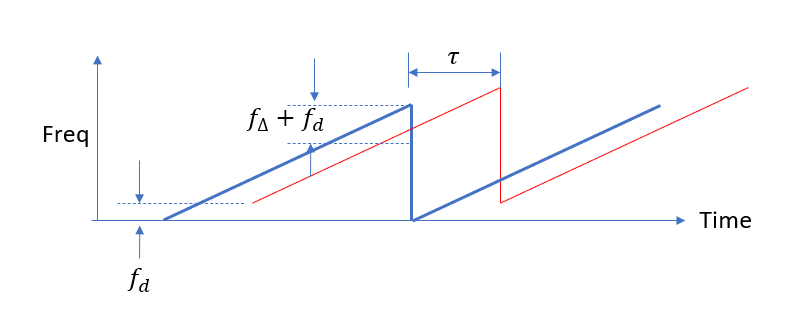
To see how Doppler offset affects the determined range, consider first the target with a constant velocity moving toward the transmitter. Assuming the frequency change over the ramp is significantly smaller than the carrier frequency transmitted (as would be typical for FMCW), the Doppler offset in this case would be constant and independent of the frequency ramp rate, shifting the frequency of the received signal higher as depicted in the graphic below and given by the formula below that.
$$f_d = \frac{2v_r f_{tx}}{c}$$
Where
$f_d$: Doppler frequency offset
$v_r$: velocity between transmitter and target
$f_{tx}$: carrier frequency of transmitter (assumed >> frequency ramp)
$c$: speed of light.
In addition to this offset, and not necessarily visible in the scale of the graphic above, the measured frequency difference after the low pass filter ($f_{\Delta}$) will be changing with time (as itself a ramp if velocity is constant). Note that there is no cross-dependence in the ramp due to the time change in range, and the offset due the Doppler frequency due to the target velocity; therefore these two effects can be computed independently and summed.
Consider our example with the transmitted frequency as 10 GHz, with a relative velocity between transmitter and receiver of 20 m/s (target moving toward transmitter) the Doppler offset would then shift the received chirp upward in frequency by:
$$f_d = \frac{2 (20) 10E9 }{3E8} = 1.33 \text{ KHz}$$
As the target is moving toward the transmitter, the frequency difference due to the range alone would be decreasing. If we assumed a case where we use all measured data was for the target from 15m range as originally derived, up to a 14 m range, or 1 meter corresponding to a time of 1/20 second (given the velocity of 20 m/s), the frequency after the low pass filter without accounting for Doppler would be 1 MHz at 15m corresponding to a 100 ns delay as computed above, and for 14m:
$$\tau = \frac{2d}{c} = \frac {2(14)}{3E8} = 93.33 \text{ ns}$$
$$f_{\Delta} = \tau R = (93.33E-9)(10E6/1E-6) = 933.3 \text{ KHz}$$
Thus the frequency difference $f_{\Delta}$ before accounting for Doppler went from 1 MHz to 933.3 KHz over the 50 ms measurement interval. As noted by the graphic above, the effect of the increase in Doppler is to decrease this measured frequency difference by a constant amount, specifically 1.33 KHz in this case, and does not change the rate of change for the measured frequency; so the actual measured $f_{\Delta}$ in this case would be a frequency ramp starting at 998.67 KHz and ending at 932 KHz. Independent of this frequency shift, we can still derive the velocity directly from the rate of change in the measured frequency.
The above is to show that the ramp of the chirp itself can be removed from the equation with Doppler and velocity determination based on the derived waveform for $f_{\Delta}$, simplifying the computation.
Combining the above to a final formulation, we get:
$$d = \frac{c \tau}{2} = \frac{c (f_{\Delta} + f_d)}{2R} =\frac{c f_{\Delta} + 2v_r f_{tx}}{2R}$$
Where
$R$: Ramp rate of chirp
$f_d$: Doppler frequency offset
$f_{\Delta}$: Measured frequency after low pass filter in receiver
$f_{tx}$: carrier frequency of transmitter (assumed >> frequency ramp)
$c$: speed of light.
And $v_r$ is derived directly from the time rate of change in $f_{\Delta}$, which is not affected by a constant Doppler or other parameters as described above.
A time varying velocity would result in the following differential equation:
$$v_r = \dot{d} = \frac{c}{2R}(\dot{f_{\Delta}}+2\dot{v_r}f_{tx})$$
Which for constant velocity simplifies to:
$$v_r = \frac{c \dot{f_{\Delta}}}{2R}$$
Resulting in:
$$d = \frac{cf_{\Delta}}{2R} + \frac{c \dot{f_{\Delta}}f_{tx}}{2R^2}$$
With the above computations we are assuming the receiver bandwidth is wide enough and time resolution for all processing small enough to support the rate of change due to the velocity of the target, otherwise these effects can also significantly impact the result.
[NOTE: I derived the above result while writing this post and did not yet confirm with a reference, simulation or other source. There could easily be sign or factor of 2 errors so please confirm my derivation carefully. I will remove this note once I have otherwise validated the result]
A useful reference on FMCW and other radars is this write-up by Infineon.


