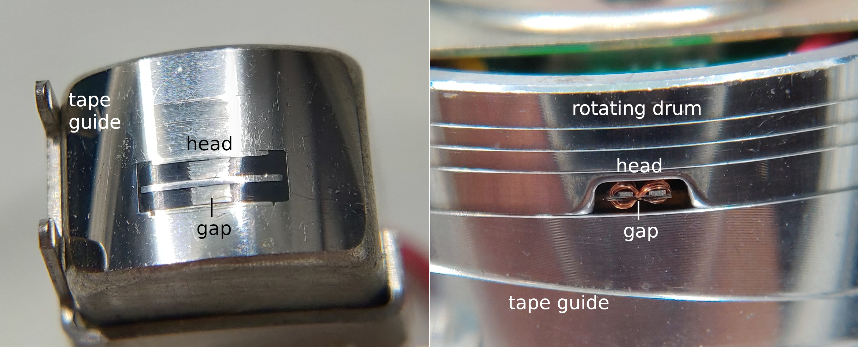
High-capacity tape formats use helical scanning. Here I look at why that gives a higher capacity than linear recording with four tracks (one stereo track on each side) like in a compact cassette (C-cassette).

Figure 1. Stereo C-cassette player/recorder linear head (left) and a helical scanning head from a data drive (right), same scale. There is a too-short-to-see gap between two polished surfaces of laminated magnetic cores that concentrate the magnetic fields to the inside of the coils and to a thin line on the coated surface of the tape. In case of linear scanning, the head gap is oriented straight across the tape.

Figure 2. A simplified illustration of the tracks on a four-track tape (left) and helical scanning tape (right). In reality there needs to be some space, "guard bands", between the linear scanning tracks to prevent leakage between the channels. In case of helical scanning this need is typically circumvented by having heads that read/write consecutive tracks in different gap angles. This way the magnetizations will be approximately orthogonal and nto sensed by the wrong head.
It's not about the speed at which the recording head travels. It is possible to slow things down and record the same spatial wavelengths, only it would take a longer time to do that or to read the recording later. Recording faster does not increase tape capacity. What it does is it gives a higher data rate which is important for practical applications. Also, for analog recording, a high head travel speed may be needed because the analog signal has a high bandwidth. Very small spatial wavelengths are difficult to record because of the magnetic grain size on the tape and because of mechanical design considerations.
For information density, it doesn't matter what the angle of the tracks on the tape is. So for a simplified analysis we can rotate the helical scanning tracks to be horizontal, and we can look at just a 1/4 of the tape and consider that as a single-track tape in case of the C-cassette:

Figure 3. One-track linear recording tape (left) and an n-track linear recording tape (right).
Let's write a spatial version of the Shannon–Hartley theorem that suits our simplified analysis:
$$C = nB \log_2 \left( 1+\frac{S}{nN} \right)\tag{1}$$
Here $C$ is the total capacity (bits/m of tape), $n$ is the number of tracks, $B$ is the spatial bandwidth (1/m) and $S/N$ is the reference signal-to-noise ratio, the ratio between signal power and noise power in the reference case that there is just a single track. If we increase from the reference case the number of tracks by a factor $n$, then the track width decreases to $1/n$ times that in the reference case, giving an effective signal-to-noise ratio of $\frac{S}{nN}$ for each track. This comes from that the signal power gets divided by a factor $n^2$ and the noise power gets divided by a factor $n$. This is because each of the $n$ individual channels has the same signal power as would each of $n$ identical-signal channels that sum to the single full-width track, and because the noise is independent between the $n$ tracks so the power of the noise in the full-width track equals the sum of the powers of the noises in the $n$ tracks. So the signal-to-noise ratio goes down as the number of tracks is increased. But at the same time, the total capacity will be the sum of the individual track capacities, hence the factor $n$ in front of the formula.
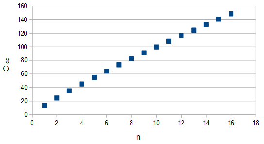
If we plot the capacity calculated by Eq. 1 as function of the number of channels, it would appear that we can increase the capacity indefinitely by just increasing the number of tracks:

Figure 4. Proportional total capacity as function of the number of tracks, for an out-of-the-hat signal-to-noise ratio of 50 dB in case of a single track. Calculated using Eq. 1.
The main thing that is wrong with this analysis is that the size of the magnetic grains is not truthfully infinitesimally small, so there will be all kinds of unaccounted for trouble (correlated noise between tracks and noise being far from Gaussian assumed by Eq. 1) if the tracks become too narrow and densely spaced. But the result still holds up to some limit, that more and narrower tracks can store more information even when each has a lower signal-to-noise ratio than would a single, or four, tracks. So it is not just that we wouldn't have come up with the right modulation scheme for C-cassettes. The design of data tape formats with helical scanning really is superior in terms of information capacity expressed per tape length, for the same width of tape.
John C. Mallinson, The Foundations of Magnetic Recording, 2nd edition 1993, Academic Press, USA, p. 129, gives a result identical to Eq. 1, and also postulates a limit:
9.8 Ultimate Information Areal Capacity
Consider a tape of unit width, divided, without guardbands between the tracks, into $M$ parallel tracks as shown in Figure 9.9. Clearly, the combined Shannon areal capacity is
$$C(M) = MB\log_2\left(1 + \frac{(\text{SNR})_w}{M}\right),\tag{9.13}$$
where $(\text{SNR})_w$ is the wide-band signal-to-noise ratio when the full tape width is used for a single track ($M = 1$). For unit head–tape relative speed, the bandwidth $B$ is the reciprocal of the minimum wavelength, $\lambda_\text{min}$. It is obvious from this expression that the areal capacity increases as $M$ increases. The ultimate storage capacity, in bits per unit area, occurs when the number of tracks becomes very large, and it is
$$\text{ultimate areal capacity} = \frac{nf^2\lambda_\text{min}}{2\pi\log_2e}.\tag{9.14}$$
For the instrumentation recorders considered in this chapter ($n=10^{15}$ particles per cubic centimeter, $f = 0.2$, and $\lambda_\text{min} = 60 \mu\text{in.}$), the ultimate capacity is, amazingly enough, $10^9$ bits per square centimeter or 6000 megabits per square inch. This is an extremely high areal density in comparison with present achievements in digital recording, where figures in the range of 50–150 megabits per square inch are the norm.
