2
$\begingroup$

Original image Blurred image

I can't figure out what type of blur such an image has and how I would be able to generate it in python. I would be grateful for any help.

I tried Gaussian blur, bokeh blur, Wolf and Born out of focus model, disk blur, but it didn't give a similar result

$\endgroup$
6
  • $\begingroup$ this looks very much out of focus, so the question is whether you paramerterized your out-of-focus blurs correctly. $\endgroup$ Commented Apr 22 at 11:32
  • $\begingroup$ Yes, I have tried several models of out of focus blur, however they are closer to Gaussian blur than the one I quoted. And it would be cool if someone could tell me which model could be used to generate such blurs. $\endgroup$
    – empirefloo
    Commented Apr 22 at 11:50
  • 1
    $\begingroup$ Do you have the original picture? This is a lot easier to assess if you have both the before and after. $\endgroup$
    – Hilmar
    Commented Apr 22 at 16:14
  • $\begingroup$ @Hilmar, Yes I have the original image, I tried to get a blur kernel through Fourier transform division in the frequency domain, however applying such a kernel to other original images did not give a good enough result compared to their blurred versions. Perhaps obtaining the kernel in this way is a rather crude way. Perhaps you know a better way? $\endgroup$
    – empirefloo
    Commented Apr 22 at 18:24
  • $\begingroup$ Could you post that original image? Did you look at the kernel you estimated? It likely is very noisy, some regularization is usually necessary, see Wiener filter. $\endgroup$ Commented Apr 22 at 19:54

3 Answers 3

3
$\begingroup$

Assuming we're dealing with a linear filter, we can use deconvolution to find the kernel. Usually, deconvolution operations estimate the original input image $f$ in the operation $f*h=g$, given the kernel $h$ and the blurred image $g$. But since convolution is commutative, we can simply change the places of $f$ and $h$. This means we can use standard deconvolution tools to compute the kernel form an input and output image pair:

import diplib as dip


input = dip.ImageRead('input.jpg')
blurry = dip.ImageRead('blurry.jpg')

# Use green channel to compute kernel
kernel_estimated = dip.WienerDeconvolution(blurry(1), input(1), regularization=1e-9, options={"pad"})
kernel_estimated.Show()

I'm using DIPlib here, because this is what I'm familiar with (disclosure: I'm an author), but you can use any library for this that does deconvolution. I used a very small amount of regularization because there's little noise other than JPEG compression artifacts. You can manually increase this value until noise doesn't dominate the output. If it's too large, the output will be too smooth, and the kernel will then to look like a Gaussian.

This is the result:
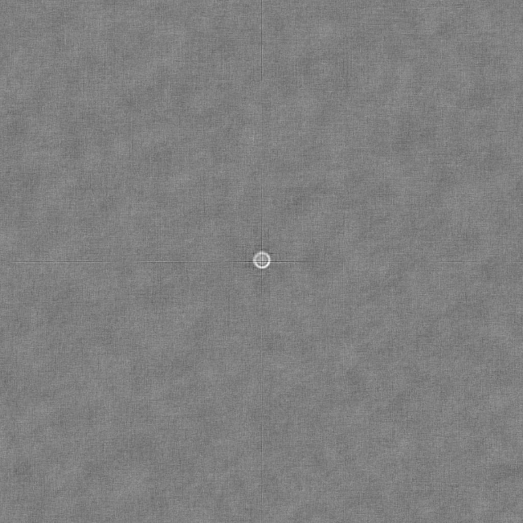
estimated convolution kernel

The cross is likely caused by JPEG compression artifacts. The gray background is just noise around the 0 value, there exist negative values in this image.

We also notice that the kernel is shifted. This means that the input and output are not aligned.

With negative value set to 0, and zooming in to the middle of the image, the kernel looks like this:

kernel

I'm not sure if it's just a ring or if the interior has some intensity.

Assuming it's just a ring (diameter is about 27, the profile looks like a Gaussian with sigma 2), we can recreate it like so:

kernel = dip.Image((35, 35), 1, "SFLOAT")
kernel.Fill(0)
dip.DrawBandlimitedBall(kernel, diameter=27, origin=(35//2, 35//2), mode="empty", sigma=2)
kernel /= dip.Sum(kernel)

out = dip.Convolution(input, kernel)
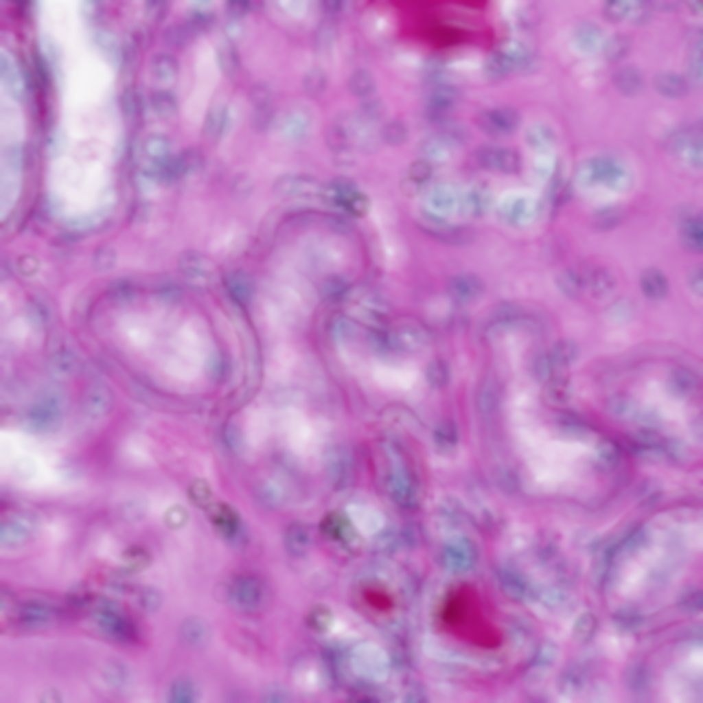
output of convolution above

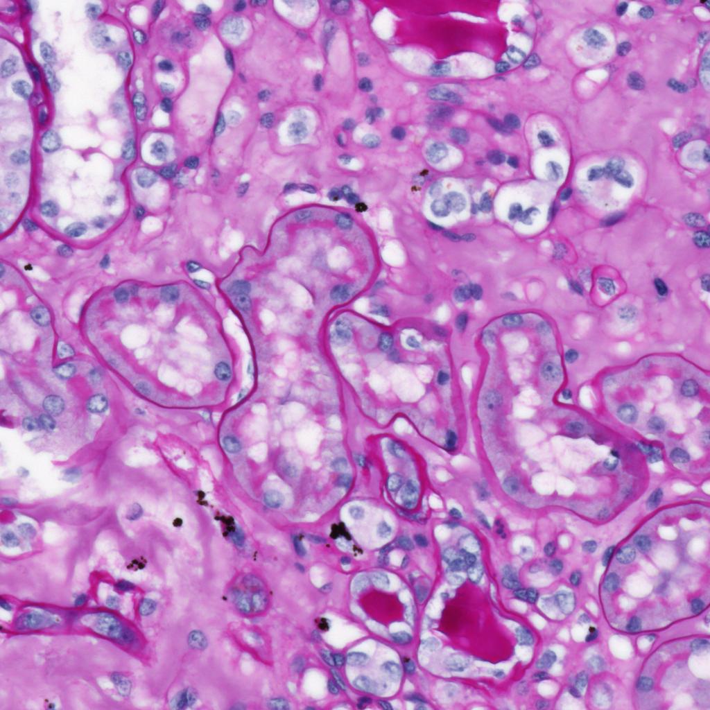
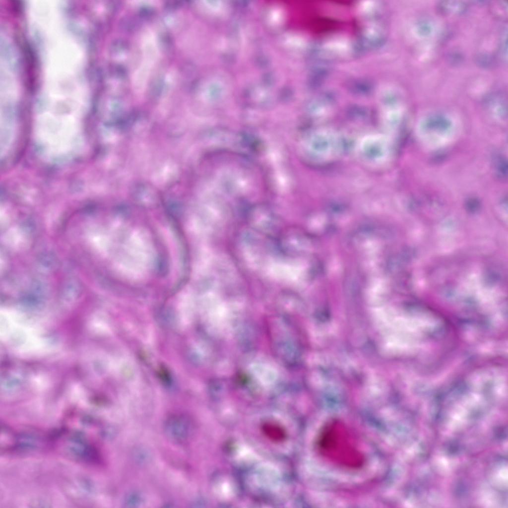
This does not look exactly like the blurry image, but has similar properties. I might have misjudged the ring diameter, we might need to fill up the ring with an intermediate gray value, maybe our ring is too smooth, and maybe there's a different kernel for the red and blue channels.
$\endgroup$
0
$\begingroup$

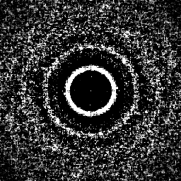
If we do cepstrum processing using my Imagemagick 7 script (see http://www.fmwconcepts.com/imagemagick/cepstrum/index.php) we get

cepstrum -G -c 100000 img.jpg cep.png

where -G indicates gray level output and -c is the scaled log for the spectrum.

enter image description here

The (central) ring in the image indicates likely camera defocus and if so, the the diameter (66 px) is twice the diameter needed for deconvolution using and ideal camera with ideal defocus in the frequency domain and a Wiener filter.

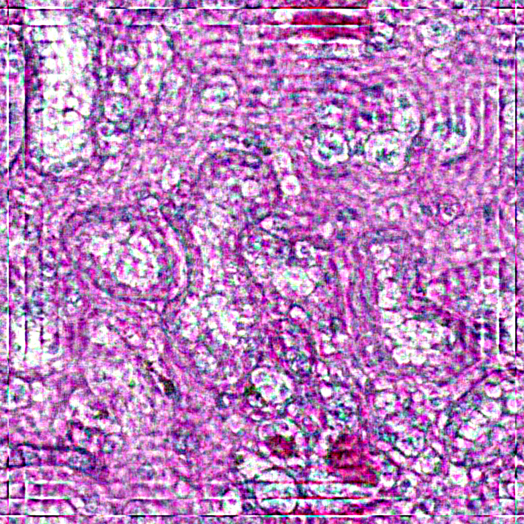
Using my script, cameradeblur (http://www.fmwconcepts.com/imagemagick/cameradeblur/index.php), I get

cameradeblur -a 33 -n .0005 img.jpg dblur.png

where -a is the diameter of defocus and -n is a small noise constant for the Wiener filter. Note that I have posted a JPG in place of the resulting PNG, which was too large for posting.

enter image description here

For reference, see my FFT processing tutorial for more information about the cepstrum and cameradeblur processing.

http://www.fmwconcepts.com/imagemagick/fourier_transforms/fourier.html

Note that there is some ringing at the edges due to imperfect processing. Increasing the noise estimate will reduce the ringing, but not sharpen as much.

$\endgroup$
0
$\begingroup$

Reading your images and turning into pseudo luminance:

im1 = imread('X7xW7.jpg');
im2 = imread('EfBs7.jpg');
im1_gray = mean(im1, 3);
im2_gray = mean(im2, 3);

Estimate a blur kernel using least squares, to be defined further down:

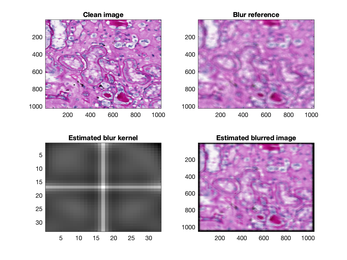
h_hat = array_deconv(single(im1_gray), single(im2_gray), [33 33]);

Generate an approximation to the blurred image using the estimated kernel:

im2_hat = convn(h_hat, double(im1));

Turn 2-d convolution into a matrix multiplication, and solve inversion via Least Squares:

 function h_hat = array_deconv(x, y, h_size)
 x_pad = zeros(size(x)+h_size-1);
 N2 = (h_size-1)/2;
 x_pad(N2(1)+1:end-N2(1), N2(2)+1:end-N2(2)) = x;
 x_buf = zeros(prod(h_size), 0);
 for (col = N2(2):size(x_pad, 2)-N2(2)-1)
    for (row = N2(1):size(x_pad, 1)-N2(1)-1)
        tmp = x_pad(row+(-N2(1)+1:N2(1)+1), col+(-N2(2)+1:N2(2)+1));
        x_buf(:,end+1) = tmp(:);
    end
 end
 h_hat = lsqr(x_buf', y(:));
 h_hat = reshape(h_hat(end:-1:1), h_size);
 end

Results: enter image description here

Not perfect (the blurred image contains too sharp high-contrast "lines". Perhaps my blur kernel is too small?). But I like that it contains no ringing artefacts typically associated with frequency domain approaches.

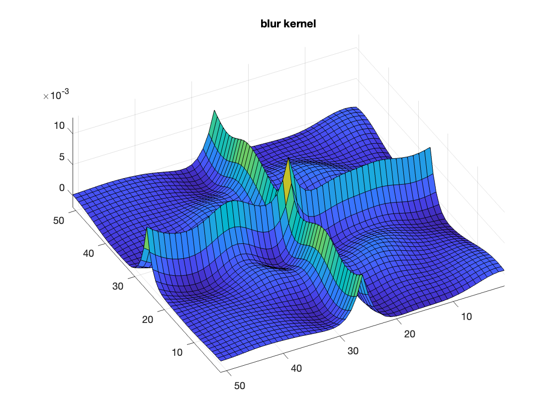
Another visualisation of my estimated blur kernel: enter image description here

It seems like a "cross" with somewhat wavy amplitude, on top of a smooth circular "donut". I was expecting something like a Bessel function (camera out of focus).

$\endgroup$

Your Answer

By clicking “Post Your Answer”, you agree to our terms of service and acknowledge you have read our privacy policy.

Not the answer you're looking for? Browse other questions tagged or ask your own question.