0
$\begingroup$

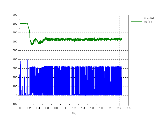
My question is tightly related to my different question. Let's say I have an inverter fed three phase induction motor drive where in the braking phase (when the motor operates in a generator mode) the generated electrical power is dissipated in the braking resistor controlled via simple chopper. Below is a record of the braking chopper operation.

enter image description here

I need to implement a software based thermal protection of the braking resistor. Unfortunately there is no temperature sensor installed in the braking resistor. So I has to somehow estimate the temperature.

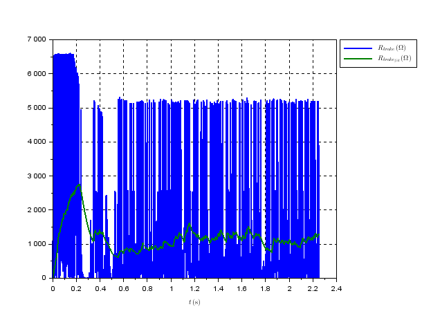
My first idea how to do that was to exploit the measured dc link voltage and the current through the braking resistor and calculate resistance of the braking resistor via the Ohm's law. Then I can derive its temperature from the temperature dependancy of the resistance. I have attempted to experiment with this approach but I have received huge spikes of the resistance value. The results aren't much more better neither in case I filter the resistance values via the simple first order low pass filter with time constant 1 s (from my point of view reasonable value)

enter image description here

Does anybody see any way how to get more reliable resistance values via the method I have described above?

$\endgroup$
7
  • $\begingroup$ Did you exclude the time when your chopper was "off" from the bottom curve? $\endgroup$ Commented Mar 11 at 14:01
  • $\begingroup$ No, I didn't. During those intervals I use the last calculated value of the resistance from the interval when the chopper was on. It is a question whether it is correct approach. $\endgroup$
    – Steve
    Commented Mar 11 at 14:48
  • $\begingroup$ try excluding them. Holding the last value is pretty certainly a bad idea. $\endgroup$ Commented Mar 11 at 14:50
  • $\begingroup$ What value do you suggest to use instead for the resistance during the off time periods? I have been thinking about a real-time algorithm for the temperature estimation. $\endgroup$
    – Steve
    Commented Mar 11 at 15:11
  • $\begingroup$ none at all. You simply don't estimate during that time. $\endgroup$ Commented Mar 11 at 15:17

1 Answer 1

1
$\begingroup$

Typically a fairly simple thermal model should suffice.

$$ T_{\Delta}[n] = a\cdot T_{\Delta}[n] + (1-a)\cdot P[n]\cdot R_T \tag{1}$$

where $T_{\Delta}$ is the current temperature rise over ambient of the resistor, $P[n]$ the instantaneous power, $R_T$ the thermal resistance, and $a = e^{-\tau \cdot f_s}$, where $\tau$ is the thermal time constant of your system and $f_s$ the sample rate.

The instantaneous power can be calculated as either $v^2[n]/R$ or $i^2[n]\cdot R$. You can try to determine $R_T$ and $\tau$ through the modelling the thermal mass and thermal resistance to ambient but the easiest here is to just measure it using a unit step.

The trickiest part here is probably to pick a suitable sample rate. Your voltage/current signal has a fair bit of high frequency content and squaring it doubles the bandwidth again. You need to sample this without aliasing, so I would go rather high here (if you can reasonably afford it).

A few points:

  1. Note that this model will only give you the temperature difference between the resistor and the ambient temperature, not the absolute temperature of the resistor. If your ambient temp moves, so does the entire model.
  2. The resistance often depends on the temperature. If this effect is large enough to matter, you can include it in the model as simple linear model like $R(T_{\Delta}) = R_0 + \alpha T_{\Delta}$
  3. The thermal is typically time constant will be much much slower than the sample rate, which can lead to numerical problems especially if you do fixed point processing. One way to avoid this is to down sample the power signal by a large number before applying the rest of the processing.
$\endgroup$
1
  • $\begingroup$ Thank you very much for your answer. I have been still thinking about estimation of the temperature. It seems to me that the method I have proposed above is suitable for that purpose but I have been strugling with the resistance calculation. $\endgroup$
    – Steve
    Commented Mar 12 at 12:51

Your Answer

By clicking “Post Your Answer”, you agree to our terms of service and acknowledge you have read our privacy policy.

Not the answer you're looking for? Browse other questions tagged or ask your own question.