If your signal is relatively narrow band (does not occupy the entire Nyquist bandwidth) then an FIR filter would be more efficient to compute the band-limited Hilbert Transform vs an FFT which provides a reasonable Hilbert Transform over (nearly) the full Nyquist Bandwidth, and specifically if the FIR Hilbert can be implemented with 19 taps or less, which would be based on filter bandwidth required and performance accuracy needed. (See comparison of resources at the end of this post).
If implementing with an FIR filter, choose an odd length so that the compensating delay for the real part of the analytic signal is an integer number of taps.
The remez function in Python scipy.signal (firpm in Matlab and Octave) supports generating Hilbert’s directly with arbitrary bandwidths, so this provides an easy approach for the novice. There are many other alternate FIR based solutions as well (see comments with further suggestions by RBJ).
For example a 51 tap Hilbert over a portion of the Nyquist band is generated as follows:
coeff= sig.remez(19, [0,.1,.2,.3,.4,.5], [0,1,0], type=‘hilbert’)
The compensating delay is 9 samples and the bandwidth is from .2 to .3 of the sampling rate.
This implements a Hilbert Transform with an implementation delay over the specified passband (here we pass .2 to .3 with weight 1 so specifies the passband), results in excellent quadrature phase and +/-0.1 dB of amplitude ripple in the passband.
The analytic signal is a complex waveform with the real part as the original signal and the imaginary part as the Hilbert Transform of the original signal. So to create the analytic signal with the FIR filter above, a 25 sample delayed copy of the input signal represents the delay matched real output of the analytic signal, and the filtered output (as the Hilbert Transform) represents the imaginary output of the analytic signal.
With this solution (or any FIR based Hilbert such as other suggestions recommended by RBJ in the comments) the OP can use an FIR length up to the duration of the buffer but should be one less to be odd length for a significant improvement in processing required. (So up to a 127 length FIR filter). With an odd length filter, the solution will have every other coefficient as 0 including the center tap, but is also an anti-symmetric filter meaning the negative of the first half of the filter will be the same coefficients as the last half of the filter. For this reason the total filter length $N$ should be three more than an integer multiple of 4, as otherwise the first and last coefficient will just end up being zero (so use $N$ such that $(N-3)/4$ is an integer, 127-3 is a multiple of 4, so 127 works). Also with an odd number of coefficients, the delay matched path is an integer which significantly simplifies the delay matching. However, as an FIR filter, a single new output sample is computed based on the FIFO contents (which becomes the filter's memory) after every delta T.
Based on the above points, I will compare resources needed based on an estimate of the number of multiplications and additions compared to the FFT/IFFT approach assuming the OP did maximize the FIR length to 127 coefficients, compared to an FFT of 128 samples. (So $N=127$ and we wish to have a result $N+1=128$ long).
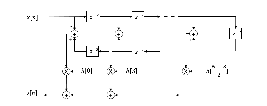
With the Hilbert FIR, every other coefficient including the center tap is 0 and then due to the assymetry in the coefficients, only half the number of multiplications is required. For $N$ coefficients this results in $(N-3)/2$ real multiplications and $N-3$ real additions, so for 127 coefficients this would be 62 real multiplications, and 124 real additions as shown in the block diagram of the resulting FIR implementation below.

$x[n]$ represents every new sample shifted into the FIFO on each clock sample (at each delta t). $z^{-2}$ is a 2 sample delay, so every other value in the FIFO is used at any given delta t (clock sample) to compute a new output sample $y[n]$. To compare the FFT which does the processing on a complete block, note that it will take 128 samples to fill an output buffer that is 128 samples long. Thus the total processing required to get 128 samples (when $N=127$) is $(N+1)(N-3)/2$ real multiplications and $(N+1)(N-3)$ real additions. Thus approximately $N^2/2$ and $N^2$ respectively.
For the FFT approach we do an FFT of a real sequence and then an IFFT of the complex result with half the bins zeroed out. This results in $2(N+1)\log_2(N+1)$ real multiplications and additions.
Charting this shows that it is difficult to beat the efficiency of computing the Hilbert with an FFT IFFT. The cross-over is at 21 samples, meaning if the Hilbert required could be done with a 19 tap FIR filter, this would be more efficient than using the FFT / IFFT, otherwise the FFT / IFFT would be more efficient.

Zooming in:


