3
$\begingroup$

I'm new in this community and I hope it is the right place to post my question. Unfortunately, signal processing and electronics in general are not my fields, so I'm sorry if the question is trivial.

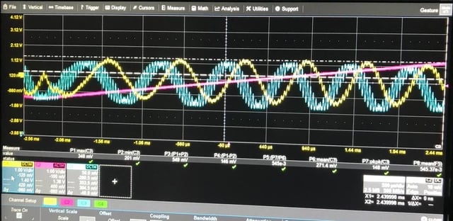
I'm detecting a signal with a photodiode, that is the blue signal in the following picture:

enter image description here

The blue signal is a sinusoid with frequency $\omega_1$ order of more or less 300 Hz, and it is modulated with a frequency $\omega_2$ (order of some kHz), with a small modulation depth $\epsilon$. This looks like a PM signal, of the type $y_{sig} = \sin(\omega_1t + \epsilon \sin\omega_2t)$.

This signal is taken and sent to a demodulation stage. Here, I think that in my lab we may not use the correct term, because for me a demodulation stage + LPF should yield by definition the original signal, but this is not what happens here. In any case, we feed the signal to a mixer, to mix it with a sinusoidal signal at frequency $\omega_2$, of the type $y_{demod} = \sin\omega_2 + \phi$, where $\phi$ is a phase that I can tune in my function generator. I then apply a Low pass filter, with cutoff frequency $\omega_{LPF}<\omega_2$.

We know from experience that this should yield the DERIVATIVE of the original signal, that in the picture is the yellow signal.

My question: I don't understand WHY the derivative is expected to come out from this demodulation+LPF sequence applied to $y_{sig}$. I expect the output signal to be something of the type $y_{out} = \sin\phi \frac{dy_{sig}}{dt}$. This is something I observe. Indeed, changing the phase $\phi$, I can tune the amplitude of the yellow signal until it vanishes. However, I don't understand HOW this expression may come out.

I thought I should calculate $y_{sig}\cdot y_{demod}$ (action of the mixer) and then get rid of the terms with frequencies $\omega_{LPF}<\omega_2$ to recover $y_{out}$. But nothing comes out of it. If you can give me some advice on how to proceed it would be very useful for me.

$\endgroup$

2 Answers 2

3
$\begingroup$

Reverse-engineering your 'photodiode-generated' signal from your picture, one can write down: $$ ω_1 = 300 \\ ϵ = \pi / 6 \\ ω_2 = 8000 \\ y_{sig}(t) = \sin(ω_1 t + ϵ\cos(ω_2 t)) $$ Notice that a "small" modulation depth parameter ϵ is not that small but still enables us to expand $y_{sig}$ into a series, as we'll see later. The signal graph:

Ysig

The signal Ysig multiplied by Ydemod produces the waveform

Ysig*Ydemod

which, when low pass filtered, mysteriously yields the DERIVATIVE of the original signal, but no traces of this enigmatic result are discernable in this waveform prior to filtration.

But let us transform the original signal $y_{sig}(t)$, using the trigonometric sum identity, BEFORE carrying out any processing on it. $$ \sin(ω_1 t + ϵ\cos(ω_2 t)) = \sin(ω_1 t) \cos(ϵ\cos(ω_2 t)) + \cos(ω_1 t) \sin(ϵ\cos(ω_2 t)) $$

Still, the graphs of two summands in the trigonometric sum identity are not a revelation

trig_identity

But look at the factors (in the summands) which depend on the carrier frequency, $\cos(ϵ\cos(ω_2 t))$ and $\sin(ϵ\cos(ω_2 t))$:

trig_identity_carrier_factors

The carrier-dependent factor $\cos(ϵ\cos(ω_2 t))$ in the $\sin(ω_1 t) \cos(ϵ\cos(ω_2 t))$ summand is nearly constant and also its frequency is a twice carrier frequency. Contribution of this summand is doomed to be filtered out. The carrier-dependent factor $\sin(ϵ\cos(ω_2 t))$ in the $\cos(ω_1 t) \sin(ϵ\cos(ω_2 t))$ summand is not a purely sinusoidal wave, but look at its derivative

$$ d/dt\left(\sin(ϵ\cos(ω_2 t)\right) = -\cos(ϵ\cos(ω_2 t))·ϵ·ω_2·\sin(ω_2 t) $$

which, for all reasonable ϵ values, is close to $-ϵ·ω_2·\sin(ω_2 t)$, the derivative of a pure cosine multiplied by ϵ. Thus, we can consider this factor a cosine in phase with the Ydemod, and this summand becomes the only contributor into the "demodulated" signal. Indeed, the difference between $\sin(ϵ\cos(ω_2 t))$ and a pure cosine $ϵ\cos(ω_2 t)$ becomes noticeable only at ϵ as great as π/2:

sin(epsHalfPi.cos(..))

Furthermore, the shape of carrier waveform when used in mixers is not required to be purely sinusoidal: the local oscillator signal is fed to mixer's switching inputs. For demodulation to be efficient, this signal and Ydemod wave must be in phase, and this condition is fully satisfied when ϕ = π/2.

The derivative-assisted interpretation also explains the factor ϵ in your $Y_{out}$:

(sincos+cossin)*Ydemod

Although $\sin(ϵ\cos(ω_2 t))$ is not a derivative of $\sin(ω_2 t)$, multiplied by ϵ for no reason, the comparison of its derivative with the pure cosine's derivative shows that $\sin(ϵ\cos(ω_2 t))$ can be reliably approximated with the function $ϵ\cos(ω_2 t)$.

Summing up, the specific "compound" formula for modulated signal, $y_{sig}(t) = \sin(ω_1 t + ϵ\cos(ω_2 t))$, "mixes up" in-phase and quadrature terms in your compound signal. We revealed this mix-up with the trigonometric sum identity analysis and discovered that the "demodulated" waveform becomes the scaled orthogonal copy of the original signal. Approximation of the $\sin(ϵ\cos(ω_2 t))$ waveform and the in-phase/quadrature "entanglement" help explain also the factor ϵ appearing in the demodulated signal Yout.

I selected a cosine as a local oscillator wave, i.e., ϕ = π/2. One can introduce the arbitrary ϕ value into the analysis paying the cost of complicated trigonometric identity formulas. Dan Boschen's answer presents the general, more rigorous, approach to solving problems of this kind.

$\endgroup$
4
  • $\begingroup$ Hi! Thanks a lot for the super detailed answer, it was very nice of you to take the time to plot all the functions and I get clearly where the contributions come from and why some of them are negligible! $\endgroup$
    – Luthien
    Commented Sep 24, 2023 at 13:17
  • $\begingroup$ Just one small clarification: without considering the filtered out contribution, we may say $y_{sig}\sim\cos(\omega_1t)\sin(\epsilon\cos(\omega_2t))$. Then, what we do is a Taylor expansion at zero $\sin(\epsilon\cos(\omega_2t)) = \sin(\epsilon\cos(\omega_2t)) + d/dt(\sin(\epsilon\cos(\omega_2t)) )t + \text{higher orders}$. Then for small $\epsilon$ we are left just with $d/dt(\sin(\epsilon\cos(\omega_2t)) )t$, am I correct? $\endgroup$
    – Luthien
    Commented Sep 24, 2023 at 13:17
  • 1
    $\begingroup$ Absolutely! well, and this 'small clarification' proves the point and makes all these plots of mine unnecessary and superfluous. But we must give other people a chance, rather than the obvious hint, isn't it? Exactly as you did -- you gave me a chance to earn +25 points ;) $\endgroup$
    – V.V.T
    Commented Sep 24, 2023 at 14:38
  • $\begingroup$ Oh, it was actually better for me to understand what happens through your plots! Thanks again :) $\endgroup$
    – Luthien
    Commented Sep 24, 2023 at 23:29
2
$\begingroup$

There is no derivative when using a mixer and low pass filter for phase demodulation. There will be inevitable delay with the filtering and overall set-up which corresponds to a frequency dependent phase shift. This could translate a sine input to a cosine output appearing as a derivative. Also as detailed below, a 90 degree shift is required between the local oscillator and RF input to operate in the demodulators linear region for phase to amplitude translation of small angle modulations.

For small angle modulations, a multiplier (mixer) and low pass filter will provide the phase from the carrier as given by the sine product rule:

$$\sin(\alpha)\sin(\beta)= (0.5\cos(\alpha-\beta)- 0.5\cos(\alpha+\beta)$$

So if we multiply with the carrier we would get the sum and difference as:

$$\sin(\omega_1 t+\theta(t))\sin(\omega_1 t)= 0.5\cos(\theta(t))+ 0.5\cos(2\omega_1 t+ \theta(t))$$

After low pass filtering we just get the difference (assuming the variation of the phase $\theta$ with time is below the cutoff of the low pass filter):

$$y(t)= 0.5\cos(\theta(t))$$

In practical implementation with analog mixers (if done in the analog) the 0.5 is part of an overall conversion loss and results in a scaling constant for the output. Further the local oscillator (LO) port is typically driven into saturation but any amplitude variation on the other (RF) input port will translate to an amplitude variation on the output- which is indistinguishable from the phase being measured (so be careful to note if there are AM components as well in the carrier that would effect the result).

Assuming a constant envelope carrier, the OP’s result would be:

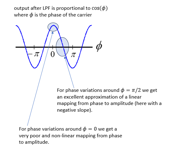
$$\theta = \epsilon\sin(\omega_2 t)$$ $$y(t) = K\cos(\epsilon\sin(\omega_2 t))$$

Where $K$ is a scaling constant.

The demodulator works best when the phase of the carrier varies around a mean value of $\pi/2$ relative to the local oscillator (so in quadrature), as at that phase offset the $\cos(\phi)$ result has an approximately linear translation from angle to magnitude. In the OP’s case if $\epsilon$ is very small, such that the angle modulates around 0, the demodulator output will instead be nearly constant with little sensitivity to variation in the phase. This is remedied by adding a $\pi/2$ shift to the local oscillator, which is essentially generating a cosine instead of a sine, and resulting in an output that is

$$y(t) = K\sin(\epsilon\sin(\omega_2 t))$$

Thus with small $\epsilon$ we can use the small angle approximation $\sin(\phi) \approx \phi$ and the result would be:

$$y(t) = K\epsilon\sin(\omega_2 t))$$

Summary in graphics:

cosine result

Note: For large angle or arbitrary angle demodulation, two mixers are used with two local oscillators in quadrature (quadrature demodulation) providing the ability to resolve the angle over a full $2\pi$: one mixer+lpf provides the cosine of the angle, and the other provides the sine of the angle, resulting in $cos(\theta)+j\sin(\theta)=e^{j\theta}$.

$\endgroup$
3
  • $\begingroup$ Hi, thank you for your comment. The "demodulator" is a frequency mixer: minicircuits.com/pdfs/ZAD-8+.pdf. It does not look as it is the same thing. Does it still make sense to you? $\endgroup$
    – Luthien
    Commented Sep 22, 2023 at 9:46
  • $\begingroup$ Thanks for the clarification- I understand and will update my answer $\endgroup$ Commented Sep 22, 2023 at 14:29
  • $\begingroup$ Thanks a lot for taking the time to answer, I'm redoing the calculations now! This is really useful, it really helps improving my understanding on how signal processing works $\endgroup$
    – Luthien
    Commented Sep 24, 2023 at 13:22

Your Answer

By clicking “Post Your Answer”, you agree to our terms of service and acknowledge you have read our privacy policy.

Not the answer you're looking for? Browse other questions tagged or ask your own question.