3
$\begingroup$

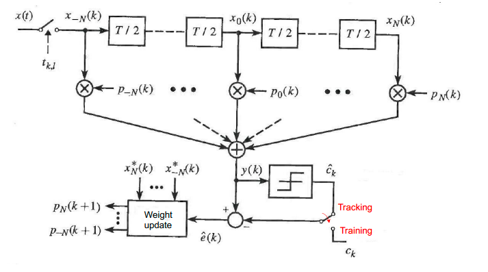
I'm trying to implement a fractionally spaced equalizer to mitigate the effect of ISI on the signal. The block scheme that I'm following is:

enter image description here

I'm using the LMS algorithm to update the tap weights. In the scheme, the algorithm has $2$ phases: the training phase, in which a known training sequence is used and the iterative equation for updating the tep weights is:

$$ \begin{align} & p_{l} \!\left( k + 1 \right) = p_{l} \!\left( k \right) - \gamma e \!\left( k \right) x_{l}^{*} \!\left( k \right), ~~~~~~~~~ -N \leq l \leq N \tag{1.1} \label{1.1} \\ & e \!\left( k \right) = y \!\left( k \right) - c_{k} \tag{1.2} \label{1.2}, \end{align}$$

and the tracking phase, in which we use a vector of symbols denoted as $\hat{c}$ and the iterative equation is:

$$ \begin{align} & p_{l} \!\left( k + 1 \right) = p_{l} \!\left( k \right) - \gamma \hat{e} \!\left( k \right) x_{l}^{*} \!\left( k \right), ~~~~~~~~~ -N \leq l \leq N \tag{2.1} \label{2.1} \\ & \hat{e} \!\left( k \right) = y \!\left( k \right) - \hat{c}_{k} \tag{2.2} \label{2.2} \end{align}$$

My question is: what are the symbols $\mathbf{\hat{c}}$? They are the output of the decision block which has in its input $y \!\left( k \right)$ (the output of the equalizer), but I don't understand how this block decides which elements of $y \!\left( k \right)$ to keep and which one to throw away.

$\endgroup$
5
  • 2
    $\begingroup$ Why don't you just implement a fractional-sample-precision delay using normal techniques and then adjust the delay in such a way that minimizes error? Why are you using the LMS adaptive filter for this. $\endgroup$ Commented Jul 19, 2023 at 21:19
  • $\begingroup$ Because it's one the main requests for the project, to implement the FSE filter using LMS algorithm to update the weights. I have read that it's maybe less complex to implement a fractional-sample-precision delay but i have no choice. $\endgroup$
    – Obsidian
    Commented Jul 20, 2023 at 7:37
  • 1
    $\begingroup$ The decision device depends on the modulation scheme that you are using. If it is QPSK for example you can use the sign function on the real and imaginary parts. $\endgroup$
    – Harris
    Commented Jul 20, 2023 at 21:47
  • $\begingroup$ I'm using a BPSK modulation scheme $\endgroup$
    – Obsidian
    Commented Jul 25, 2023 at 14:32
  • 1
    $\begingroup$ @ZaellixA Thanks for the edit. I was just about to do the same. :-) Obsidian, please use MathJax for equations, do not use images. $\endgroup$
    – Peter K.
    Commented Dec 22, 2023 at 12:20

1 Answer 1

1
$\begingroup$

This implementation assumes timing has already been properly established (as given by $t_{k,l}$) and $\hat{c}_k$ is the decisions made at the proper sampling locations for the symbol decisions at one sample per symbol.

$\hat{c}_k$ are the decisions which are used to keep the equalizer converged during "Tracking" mode, and can also be used for Decision-Directed approaches for blind equalization when sufficient SNR allows (I don't recall the exact SNR threshold for convergence but believe it is on the order of 1E-2 to 1E-3 error rate--- basically most decisions are good enough to make up for the occasional bad ones, and then the equalizer can improve this to much lower error rates by removing the inter-symbol interference component). In this case the hard limit decisions on the real and imaginary portions of the signal map to what the desired output would be if the equalization was 100% effective (resulting in zero error $\hat{e}(k)$ and thus the equalizer will have converged with no further unpdates).

Under worst conditions of degraded SNR due to excessive ISI (inter-symbol-interference - for those familiar with eye diagrams, when the eye is completely closed) - the equalizer needs to be trained with a sounding sequence in order for it to converge. Such a sequence should be spectrally rich (psuedo-random patterns that fill the channel spectrum evenly are ideal). In this case $c_k$ are the known samples from the sequence as they would appear as a multi-samples per symbol waveoform at the particular location in the receiver where the equalizer is applied. In this operational mode I would advocate for using all samples of the received waveform, comparing to the reference waveform at the same higher samples per symbol rate for determining the errors $\hat{e}_k$ to converge the waveform (and there should be an equalizer tap after every fractional delay as well, the diagram isn't clear about this). Even when switched to decision-directed (tracking mode), this can also be done at the higher sampling rate by predicting what the samples would be in between the decision samples which occur once per symbol if the additional delay matching is acceptable (in other words pass the decision samples through the same pulse shaping process such as a raised cosine pulse shaping filter if equalizing after the matched filter in a receiver using root-raised cosine filtering in the transmitter and receiver).

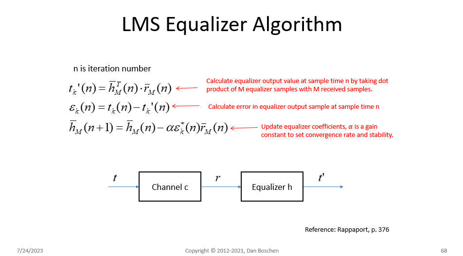
As a reference for the implementation of the LMS Equalizer, see Rappaport "Wireless Communications Principles and Practice" p. 376, with the further notations in my graphic below. The bars over variables represent arrays of $M$ samples, which is the length of the equalizer filter.

LMS Equalizer Algorithm

$\endgroup$

Your Answer

By clicking “Post Your Answer”, you agree to our terms of service and acknowledge you have read our privacy policy.

Not the answer you're looking for? Browse other questions tagged or ask your own question.