1
$\begingroup$

I have been reading The Scientist and Engineer's Guide to DSP to learn how to create filter kernels with an arbitrary frequency response (I design the magnitude response by hand). The method proposed in the link is:

  1. Create an array that describes how you want to multiply the magnitudes of each bin in the frequency domain to achieve the desired response
  2. Create a corresponding phase array of all zeros
  3. Convert mag and phase to rectangular coordinates
  4. Take the inverse DFT using the rectangular arrays to get the impulse response
  5. Roll and window the impulse response to get the filter kernel

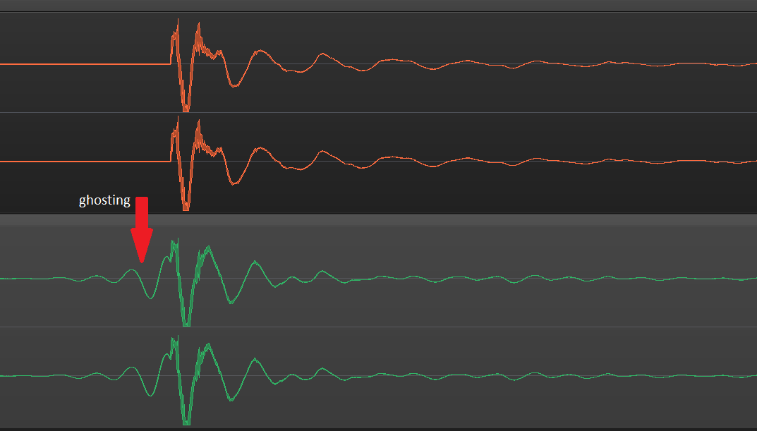
This method works well, except that I have recently realized it produces a filter that is non-causal. This is problematic for the audio processing I am doing on drums because it results in an audible ghosting of the drum hit before it actually hits:

enter image description here

I started digging into another source on this at DSP Related and realized The Scientist and Engineer's Guide to DSP probably has me creating a zero-phase filter which is a special case of linear-phase filter that apparently cannot be causal.

Thanks to an answer to a related question, I have figured out how to create a minimum phase version of my filter that is causal, however, I am still curious if there is a simpler way to create a linear-phase version that is not zero-phase so that it can be causal. Is it possible, within the inverse DFT workflow outlined above, to simply set the phase array and processes the resulting kernel in a particular way such that the result is a causal, linear-phase filter with the magnitude response I want? My suspicion is "yes", but I am struggling to find a source that outlines exactly how I would achieve this.

Here's what I've tried:
Following the original steps I outlined, I do the following:

shift = filter_size // 2
phase = np.zeros_like(desired_mag)
kernel_Z = polar_to_rect(desired_mag, phase)
kernel = np.fft.irfft(kernel_Z)
kernel = np.roll(kernel, shift)[:filter_size] * np.hanning(filter_size)

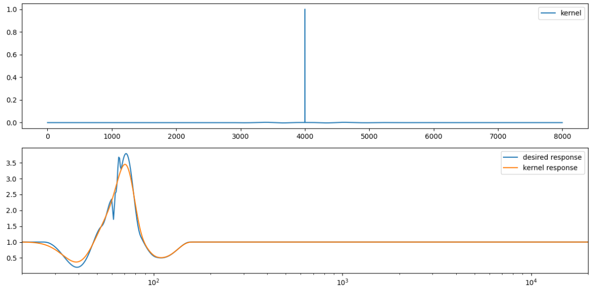
This gets me the following kernel:

enter image description here

This has the magnitude response I want, but as you can see from the top plot, it is not causal. This is the kernel that causes the ghosting.

Next I tried adjusting the phase:

shift = filter_size // 2
phase = 2 * np.pi * shift * np.linspace(0, 0.5, len(desired_mag))
kernel_Z = polar_to_rect(desired_mag, phase)
kernel = np.fft.irfft(kernel_Z)
kernel = np.roll(kernel, shift)[:filter_size]

This gets me the following kernel:

enter image description here

This looks causal (at least if I flip it), but obviously the magnitude response is wrong, and I'm also not sure how I ought to window this.

What should I do here to get the kernel I'm after?

$\endgroup$
7
  • $\begingroup$ Well, I'm definitely not an expert in Signal Processing, so could you explain why the first kernel is not causal? Where is the 0 time in your plot, I see only values from 0 to about 8000. $\endgroup$
    – ZaellixA
    Commented Jun 3, 2023 at 16:14
  • $\begingroup$ I am also far from an expert, but basically "0" is actually at 4000, right where that large peak of the filter kernel is. And I guess its hard to see in that plot but there are non-zero values extending out from either side of that peak, which means it'll be including future samples. I believe I need a filter that has its peak at one end of the kernel. Not being an expert, I also am not really sure what the implications of it being at one end over the other are, except that I would just need to convolve in the right direction so the peak is at the latest time. $\endgroup$ Commented Jun 3, 2023 at 16:37
  • $\begingroup$ You're always producing a causal filter. The linear phase filter has a large delay and pre-ringing, which is something you want to avoid in your application. So the solution is a minimum-phase filter. Since this has been mentioned in the answer to your previous question, I'm not sure what to add here. $\endgroup$
    – Matt L.
    Commented Jun 3, 2023 at 17:15
  • $\begingroup$ Note that a zero-phase filter automatically becomes a linear phase filter as soon as you implement it because you delay the symmetric impulse response in order to make it causal. $\endgroup$
    – Matt L.
    Commented Jun 3, 2023 at 17:18
  • $\begingroup$ This answer explains another way to convert a linear phase to a minimum phase filter with the same magnitude response. $\endgroup$
    – Matt L.
    Commented Jun 3, 2023 at 17:24

1 Answer 1

3
$\begingroup$

The method as described produces a zero-phase filter, which is symmetric around $n=0$, i.e. $h[-n] = h[n]$. This is inherently non-causal.

You make it causal, by time shifting (i.e. delaying it). That creates a linear filter, which is indeed causal (in the system theory sense). The delay required is typically half the filter length. It is still symmetric but around around $M=(N-1)/2$ (for odd N), i.e. $h[M-n] = h[M+n]$. It's causal in the sense that $h[n] = 0, n< 0$.

However, that has two distinct problems especially for audio:.

  1. It adds quite a bit of latency which is often prohibitive in real time applications, such as a Digital Audio Workstation (DAW).
  2. While it's technically causal (otherwise you would not be able to implement it at all) it creates a lot of pre-ringing, i.e. it smears out any transients and the signal "looks" non-causal. That's simply a consequence of it's symmetry. I think that's what you call "ghosting"

All of this is aggravated by the fact that human auditory perception is logarithmic in frequency whereas the DFT works inherently on a linear frequency axis. If you want to design a filter that has good resolution at low frequency (say does something different at 50Hz as it does at 80 Hz), you will need thousands for filter coefficients, so both latency and pre-ringing can get VERY large.

Linear phase filters are great for use cases where a flat phase response is required, but they tend to be a poor choice for audio. The human ear is fairly insensitive to monaural phase but latency and pre-ringing are real problems.

That's why most audio filters are minimum phase. Instead of setting the phase to zero, calculate a minimum phase applying the Hilbert Transform to the log magnitude spectrum (or making the Cepstrum causal/one-sided). Then perform an inverse DFT. The FIR filters will still be long but they will be causal, preserve transients (at least in most cases) and it's the lowest latency you can get.

If you need to control filter length, you can start truncating after the DFT and see what you can get away with. An even better approach would be a least square error FIR design using your desired filter size. In general this will require an iterative design process and a good understanding of your requirements and trade-offs.

The best choice would be an arbitrary magnitude minimum phase IIR filters using a design method based on an iterative search algorithm (like conjugate gradient or steepest decent). However, that's mathematically VERY complicated since (for audio applications) most of the poles in the Z-plane are bunched up around $z=1$ which creates extremely steep error surfaces and poor convergence behavior.

$\endgroup$
7
  • $\begingroup$ Ah thank you for this excellent explanation! $\endgroup$ Commented Jun 3, 2023 at 17:48
  • $\begingroup$ So is there actually a difference between a linear phase and zero phase filter kernel, in terms of the array of numbers each would generate in python for the impulse response, for example? It kinda seems like they would be identical, and the thing that makes them different is simply where I define sample 0 to start? $\endgroup$ Commented Jun 3, 2023 at 18:06
  • 1
    $\begingroup$ It's a bit more complicated than that. For example, The DFT and it's inverse are periodic in time and frequency. That's when you set the phase to zero, you'll find the "pre-ringing" of your impulse response at the end of your buffer. So keeping track of where $n=0$ is quite importantn $\endgroup$
    – Hilmar
    Commented Jun 3, 2023 at 18:36
  • $\begingroup$ //"It adds quite a bit of latency which is often prohibitive in real time applications, such as a Digital Audio Workstation (DAW)."// - - - - This is curious Hil, for at least a couple reasons: 1. Live and real-time are not exactly the same thing. Live is more restrictive. Live is real-time with the additional requirement that the latency is small enough to be tolerable in a live performance context. (That latency might be as low as 6 ms for musicians on stage and, for cell phones, as high as 100 ms round trip.) $\endgroup$ Commented Jun 4, 2023 at 1:03
  • $\begingroup$ Real-time means that the processing can keep up with the input (or output in the case of synthesis) independent of the delay. Sometimes delay is simply a part of the real-time process, such as time-aligning different loudspeakers in a large venue (such as outdoor festival concerts). Sometimes the delay is in media playback when the consumer does not care about the delay. Say it's a CD or DVD playback, you need the processing to keep up with the playback data, so it has to be real-time, but you don't care about a 500 ms delay, so it need not be live. $\endgroup$ Commented Jun 4, 2023 at 1:08

Your Answer

By clicking “Post Your Answer”, you agree to our terms of service and acknowledge you have read our privacy policy.

Not the answer you're looking for? Browse other questions tagged or ask your own question.