0
$\begingroup$

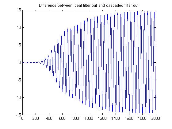
I have to compare the response of an 8th order IIR filter and its equivalent 4 stage cascaded biquad structure. A sinusoidal signal is given as input to both the systems and the output responses are plotted and the difference between the outputs of two cases are plotted.Why there is an error of the range of 15 between the output of both the cases .Code is as follows:

%%%input signal
fs=20000;
t=0:1/fs:1-1/fs;
input=2^15.*sin(2*pi*400*t);
len=length(input);%%%number of samples of the input signal 
%%%BPF spec 
bpf_order=8; %%%order of BPF (Ideal case) 
nyquist_frequency=fs/2;%%%Nyquist frequency         
lower_cutoff_freq_ch1=300/nyquist_frequency;
upper_cutoff_freq_ch1=400/nyquist_frequency;      
 [num_coeff_ch1   den_coeff_ch1]=butter(bpf_order/2,[lower_cutoff_freq_ch1 
 upper_cutoff_freq_ch1])
output=filter(num_coeff_ch1,den_coeff_ch1,input);
[sos1 G1]=tf2sos(num_coeff_ch1,den_coeff_ch1);
num_coeff_ch1=sos1((1:bpf_order/2),(1:3));
den_coeff_ch1=sos1((1:bpf_order/2),(4:6));
no_of_sos=bpf_order/2;
bpf_output=input.*G1;

 for ite=1:(no_of_sos)
         bpf_output=filter(num_coeff_ch1(ite,:),den_coeff_ch1(ite,:),bpf_output);
 end  

figure()
plot(output)
hold on
plot(bpf_output,'c*');      
signals=[output ;bpf_output];
error=signals(1,:)-signals(2,:);
figure()
plot(error) 
 

enter image description here

$\endgroup$
3
  • 1
    $\begingroup$ do you still have an open question with this? $\endgroup$ Commented Mar 12, 2023 at 14:55
  • $\begingroup$ Is there any article related to the design considerations that are to be taken care of while designing cascaded biquad filters in fixed point implementation (for testing in FPGA) $\endgroup$
    – Aami
    Commented Mar 27, 2023 at 8:44
  • $\begingroup$ This is covered in chapters in “Discrete-Time Signal Processing” by Oppenheim and Schafer, and I noted in my comment under my post upcoming courses and presentations on this specifically. But did the posting below answer your question as posted? $\endgroup$ Commented Mar 27, 2023 at 9:57

1 Answer 1

3
$\begingroup$

If you note on the upper left corner of the upper plot, the magnitude is close to 40,000. An error of 15 is not very significant. The reason we decompose (factor) the higher order filter into 2nd order sections is to decouple the poles which significantly reduces numerical precision errors (compare an error raised to the 8th power vs an error squared and added 4 times which is essentially what happens when the smaller filters are cascaded). Due to this, the “ideal” filter as described in the plot is likely the less ideal of the two and the we are seeing the limits of the floating point precision that is used (and ultimately rounding of the coefficients from their ideal values).

$\endgroup$
4
  • $\begingroup$ I believe scipy gives a nice example of this phenomenon in its documentation. They say "the numerical error pushes some poles outside of the unit circle". Is that a strange way to say what you were saying? $\endgroup$
    – NokiYola
    Commented Feb 7, 2023 at 14:39
  • 1
    $\begingroup$ @NokiYola that is not what is occurring here as the filter would be unstable in that case (but that happens as well especially in implementations with poles very close to the unit circle). What we see here is rounding error in the coefficients shifting the poles slightly but still well within the unit circle. IIR filters also enhance quantization noise (truncation at the multiplier outputs) as the errors are passed back into the filter (unlike FIR filters) so the approach to factor the filter into smaller filters is quite common for implementing IIRs for reducing that as well. $\endgroup$ Commented Feb 7, 2023 at 14:49
  • $\begingroup$ is there some litterature, key words and so on to find material in order to get a deeper understanding of this phenomenon? $\endgroup$
    – NokiYola
    Commented Feb 7, 2023 at 16:26
  • $\begingroup$ @NokiYola I suggest first understanding the details of FIR and IIR filter design without the consideration of precision errors, then understand A/D conversion and quantization noise in detail, then for IIR in particular it is very helpful to understand basic control loop theory. With that background then go into the details of fixed point design. I go through all this in courses that are routinely offered the the site dsprelated.com and I will be giving two lectures on fixed point design specific to filters at the 2023 Embedded Online Conference coming up this April. $\endgroup$ Commented Feb 7, 2023 at 17:11

Your Answer

By clicking “Post Your Answer”, you agree to our terms of service and acknowledge you have read our privacy policy.

Not the answer you're looking for? Browse other questions tagged or ask your own question.