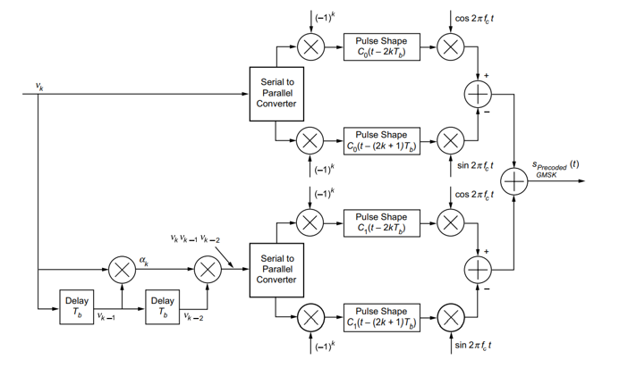
Implementation of a linear approximated GMSK block scheme based on Laurent decomposition. My goal is the Implementation of the following block scheme:
 I think $v_k$ is an NRZ element ( 1 or -1).
ovs = 4;
L = 3 % laurent decomposition
Tr = 3;% truncation length
N = 20;
a = randi([0,1],N,1);
vk = 2*a-1;
vk is an input for the first branch of this block scheme and the first S/P converter and for the second.
An input of the second S/P converter, vk_3 looks like:
vk_1 =  kron(ones(length(vk), 1), 0);
vk_1(1) = vk(end);
for i = 1: length(vk)-1
    vk_1(i+1) = vk(i);
end
vk_2 =  kron(ones(length(vk),1), 0);
vk_2(1) = vk(end-1);
vk_2(2) = vk(end);
for i = 1: length(vk)-2
    vk_2(i+2) = vk(i);
end
vk_3 = vk .* vk_1 .* vk_2;
S/P converter separate the input signal into 2: the first signal contains odd elements, the second contains the even elements. Before I apply C0 and C1 I take a product with (-1)^k and upsample the signals:
Tsym = 2* ovs; % ovs – oversampling ratio
ai_1 = vk(1:2:end);
aq_1 = vk(2:2:end);

for i = 1:length(ai_1)
    ai_1(i) = ai_1(i) .* (-1)^(i);
    aq_1(i) = aq_1(i) .* (-1)^(i);
end

ai_1 = [ai_1 zeros(length(ai_1),Tsym-1)];
ai_1=ai_1.';
ai_1=ai_1(:);

aq_1 = [aq_1 zeros(length(aq_1),Tsym-1)];
aq_1=aq_1.';
aq_1=aq_1(:);

ai_1 = [ai_1(:) ; zeros(Tsym/2,1)].';
aq_1 = [zeros(Tsym/2,1); aq_1(:)].';
The same implementation has the signal ``vk_3`.
I_1= filter(C0,1,ai_1);
Q_1 = filter(C0,1,aq_1);
IQ_1 = I_1 – 1i*Q_1
IF I take BT = 0.5, the second branch with C1 will not have a big influence of the result, so I skip its implementation.
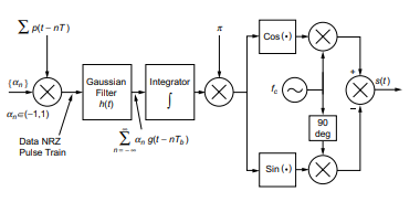
I compute a phase of the IQ_1 : unwrap(atan2(Q_1,I_1)) and compare it with a phase of GMSK transmitter (I-Q representation)

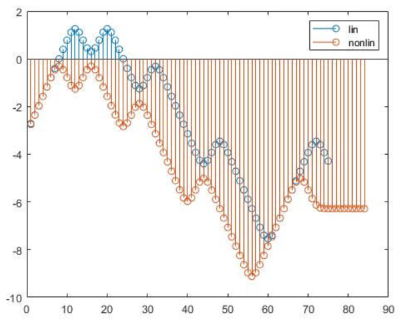
The result of the comparison:
Mr Dan Boschen explained that both produce identical results (not an approximation).
In my simulation you see I have a big difference more than 1 rad. I have mistaken in my simulation, but what the mistake is and how to find it I have no idea.
Did I implement GMSK Transmitter based on AMP wrong ( the first block)?

