5
$\begingroup$

I heard that the Direct form II transposed is better for floating-point and the Direct form I is better for fixed-point. Is it true?

I understand that DF2 and DF1T should never be used in fixed-point implementation because the poles come first resulting in overflow in these two cases. But why is DF1 better than DF2T? Is it related to the following property that DF1 avoids internal overflow?

In this book the author says that

It is a very useful property of the direct-form I implementation that it cannot overflow internally in two's complement fixed-point arithmetic: As long as the output signal is in range, the filter will be free of numerical overflow. Most IIR filter implementations do not have this property.

I understand the two's complement wrap-around example the author gives. It seems that this property has two prerequisites:

  1. There is fundamentally only one summation point in the filter.
  2. The final result $y(n)$ is in range.

The second one is easy to understand but the first one is not. What does "only one summation point" mean and why do the other forms of IIR filters not satisfy this condition?

Thank you in advance.

$\endgroup$

3 Answers 3

6
$\begingroup$

I heard that the Direct form II transposed is better for floating-point and the Direct form I is better for fixed-point. Is it true?

"Better" is a relative term, but generally yes. Direct Form II filters require less memory which is often an important consideration in floating-point calculations. Direct Form I filters require more memory, but the accumulator is never multiplied which is important in fixed-point calculations for the following reason.

Before we get into it though, there are three concepts of fractional fixed point computations that are important to understand:

  1. The absolute value of any two's complement fractional fixed point number is less than 1.

  2. Because of the first concept, it is impossible to obtain a number with an absolute value greater than 1 by multiplying two fixed point numbers, therefore it is impossible to overflow through multiplication. It is however possible to overflow through addition (e.g. $0.75 + 0.75 = 1.5$, but $0110 + 0110 = 1100 = -0.5$)

  3. If an overflow occurs during a series of additions, the final result will still be correct if an underflow also occurs before the end result. You can even double overflow through addition as long as you double underflow before the final addition. This property does not hold if there is a multiplication between the overflow and the underflow.

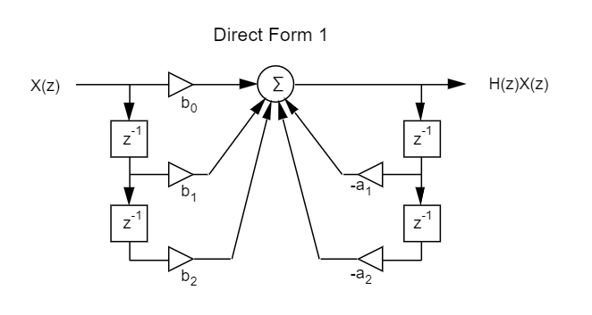
Once numbers are added together in Direct Form I filters, there are no multiplications between the additions or before the final output which means they cannot have an overflow unless the final output itself is out of range. Let's look at some example code for a Direct Form I filter to better understand this:

// This code calculates one output of a second-order IIR filter for 6 bit fixed-point calculations
a[2] = {3,4};
b[3] = {5,6,7};
x[3] = {1,2,3}; // holds current sample and previous samples
y[3] = {0,4,5}; // y[0] is the current output. y[1] and y[2] are previous outputs

// Unroll the loop to talk about it
y[0] = b[0] * x[0];    // = 5 (no overflow)
y[0] += b[1] * x[1];   // = 5 + 12 = 17 (no overflow)
y[0] += b[2] * x[2];   // = 17 + 21 = -26 (overflow :( sad day)
y[0] -= a[0] * y[1];   // = -26 - 12 = 26 (underflow...)
y[0] -= a[1] * y[2];   // = 26 - 20 = 6 (which is the correct answer, how cool!)

In this example, $y[0]$ is used as an accumulator, and the values in this accumulator are only added or subtracted, so there are no multiplications between additions and subtractions. As long as the final output is within range, you will not have any errors due to overflow within the filter. The same could not be said for Direct Form II or Transposed Direct Form II. This is why Direct Form I is usually the way to go as long as you use the proper scale factor.

One important note is that some fixed-point processors saturate overflows by default, which makes this property of the Direct Form I filter unhelpful.

$\endgroup$
1
  • $\begingroup$ I got it. The cancellation between overflow and underflow guarantees the final output is still in range. I tried to unroll a DF2T's loop and it does overflow and give a wrong result. Thank you Ryan! $\endgroup$
    – ZR Han
    Commented Aug 20, 2021 at 9:46
2
$\begingroup$

I heard that the Direct form II transposed is better for floating-point and the Direct form I is better for fixed-point. Is it true?

Mostly yes. DF1 is a perfectly good choice for floating point too. The only minor downside it that DF1 has twice the number of state variables than TF2. However if you implement cascaded biquads (which is the most common implementation), subsequent DF1 stages can share state variables. For example a 8-biquad filter needs 16 state variables in TF2 and 18 (not 32) state variables in DF1, if it's written properly.

The final result y(n) is in range.

That is an invalid argument. Regardless of topology, you have to manually scale your filter so that the output doesn't clip. DF1 offers no advantage here at all since all topologies produce the same output. In the following we will assume that the filter is already scaled not to clip the output.

There is fundamentally only one summation point in the filter

That's not wrong but still missing the point.

This is all about state variables. State variables are information that you need to store so it can be used in the calculation of the next sample, i.e. they implement the delays.

Every time you store something in memory you will have to truncate to a finite world length. That creates noise and you also need to make sure that you don't overflow.

The ONLY state variables that DF1 has are it's inputs and outputs. So if you have already made sure that your output doesn't clip, none of the state variables can clip.

Most fixed point processors used an wider word width for intermediate calculations (often referred to as "accumulator") , so clipping during the actual math is less of a concern.

TF2 has one internal state variable, and you would have to calculate the transfer function from the input to the state variable to determine whether it may clip or not. So you end up with one extra scaling step which isn't trivial to do in both analysis and implementation.

For TF2 the gain between input and state is "bounded", i.e. it cannot exceed a certain value (which I'm currently too lazy to calculate, maybe 6 or so?) that's reasonable regardless of the filter coefficients.

TF1 and DF2 are very bad since the gain is unbounded and highly dependent on the filter coefficients. Flor typical audio filters, it's not unusual to see a gain that exceeds 100 dB or more. ! This can be a real problem, even for 32-bit floating point.

$\endgroup$
6
  • $\begingroup$ One small point, Hilmar, is that when cascading second-order sections ("SOS" or "biquads") when the Direct Form 1 is used for each SOS, then the number of states is not doubled. If you have an $N$th-order IIR filter implemented as cascaded SOS, then the number of states is $N+2$, not $2N$. Of course, for a single SOS, both expressions are $4$. But for larger $N$, it's not as bad. $\endgroup$ Commented Aug 19, 2021 at 19:45
  • $\begingroup$ Thanks Hil, Sharing states is a good trick! About the bound of the gain between input and state of TF2, could you give me a hint how to calculate it and I'll do the math. $\endgroup$
    – ZR Han
    Commented Aug 20, 2021 at 8:45
  • 1
    $\begingroup$ @robertbristow-johnson: Yes, of course. I thought I explicitly stated that in my answer with my 8-stage example. $\endgroup$
    – Hilmar
    Commented Aug 20, 2021 at 20:24
  • 1
    $\begingroup$ @ZRHan. Fixed point filter scaling is complicated enough to warrant a separate question. $\endgroup$
    – Hilmar
    Commented Aug 20, 2021 at 20:25
  • $\begingroup$ Sometimes i don't read everything sufficiently carefully, Hil. $\endgroup$ Commented Aug 21, 2021 at 5:04
1
$\begingroup$

It is not terribly difficult to design in and maintain a double-wide accumulator in a fixed-point machine. e.g. two 16-bit signed numbers are multiplied to be a 31-bit signed number (0x8000 x 0x8000 is the only product of 16-bit values that needs 32 bits).

DF1

So in a single sample all of the multiplications can be done without any quantization errors. these 32-bit numbers can be added without any quantization error. there is only one single quantization point, just past the output of the 5-input adder that you can see above.

in addition, with this simple DF1 topology, simple noise-shaped quantization that gives you infinite signal-to-noise ratio at DC is also possible. It's sometimes called "fraction saving" in which the quantization is always round down (drop the bits to the right of the quantization point). Then whatever bits you dropped in the previous sample, you zero extend those bits and initialize that 32-bit adder with those bits so they get added into the current sample before quantization. This eliminates a nasty limit cycle.

$\endgroup$

Your Answer

By clicking “Post Your Answer”, you agree to our terms of service and acknowledge you have read our privacy policy.

Not the answer you're looking for? Browse other questions tagged or ask your own question.