4
$\begingroup$

Given a 2d spatial kernel $h$, I want to construct the corresponding frequency filter $H$. In theory, $H$ is simply obtained by calculating the DFT of $h$ using a FFT algorithm. But in practice, there are some considerations to be considered. First, if $H$ is used for filtering, zero-padding is required. Second, after zero padding, the original center of $h$ (i.e. center of $h$ before zero padding) must circularly-shift to the upper-left corner.

I know that zero padding is used to overcome wraparound errors. And I have observed, by experiment, shifting the original center to the upper-left corner prevents shifting the filtered image. But my question is why this is the case? That is, why not shifting the original center, leads to shifting the final image; and how shifting the original center resolves the problem?

Update:

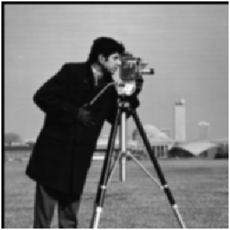
enter image description here

The above image is obtained by filtering in the spatial domain using a Gaussian low pass filter.

enter image description here

The above image is obtained by filtering in frequency domain using Fourier transform of the same Gaussian low pass filter, without circularly shifting the kernel of the filter after padding.

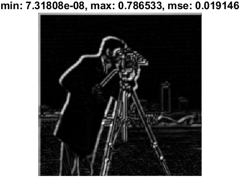
enter image description here

The above image is the absolute difference of the spatial-domain filtered image and the frequency-domain filtered image (i.e. first and second image above). As you can see, not shifting spatial kernel after padding, leads to shifting the filtered image in frequency approach.

Thanks

$\endgroup$
4

2 Answers 2

2
$\begingroup$

The Discrete Fourier Transform (DFT, what the FFT algorithm computes) has the origin in the top-left corner. It relates a time-domain signal sampled at n = 0..N-1, and a frequency-domain signal sampled at k = 0..N-1. k is assumed periodic, such that k = N is the same as k = N. The same periodicity can be assumed for n, which is why the convolution computed through the FFT is a periodic or circular convolution.

In the multidimensional DFT, the above applies to each axis individually.

The center of the kernel has to be at the origin to avoid a shift in the output. Because the origin (in our 2D case) is the top-left corner, it follows that the origin of the kernel must be in the top-left corner, with the left and top parts of the kernel wrapping around the (padded) kernel image.

The origin of the image is also in its top-left corner, but this is not relevant to the result, we don't care what the coordinate system of the input image is, because the output of the convolution has the same coordinate system.

$\endgroup$
2
  • $\begingroup$ Thanks. Can you please explain it more? By "DFT", do you mean the DFT of the image or the kernel? $\endgroup$
    – user153245
    Commented Jun 1, 2021 at 3:18
  • $\begingroup$ @user153245: I've expanded my answer a bit. I hope this clarifies things. You apply the DFT to both the image and the kernel. In both cases the origin is in the top-left corner. But where the origin is matters only for the kernel. $\endgroup$ Commented Jun 1, 2021 at 4:54
0
$\begingroup$

There are multiple answers on site which deals with your problem.

The actual solution depends on your choice for how to deal with the borders.

  1. Assume Zero Value Borders
    See Replicate MATLAB's `conv2()` in Frequency Domain

  2. Assume Circular Borders
    Applying Image Filtering (Circular Convolution) in Frequency Domain

  3. Assume Replicate Borders
    Applying 2D Image Convolution in Frequency Domain with Replicate Border Conditions in MATLAB

Of course using (1) you may implement any other border assumption.

$\endgroup$

Your Answer

By clicking “Post Your Answer”, you agree to our terms of service and acknowledge you have read our privacy policy.

Not the answer you're looking for? Browse other questions tagged or ask your own question.