0
$\begingroup$

I have a system with the transfer function given in this MATLAB code

num = [-2.341e07 -2.478e10 -1.393e12 -2.58e13 - 1.027e14 1.689e15 1.474e16 2.227e16];
den = [1 2474 1.451e06 2.622e08 1.544e10 6.874e11 2.656e13 5.294e14 4.09e15 8.13e15 3.771e15 1.122e13];
G2 = tf(num,den);

The system has 2 poles and 1 zero in the RHP. The poles are a complex conjugated pair.

ans =

   1.0e+03 *

  -1.7134 + 0.0000i
  -0.4939 + 0.0000i
  -0.2000 + 0.0000i
   0.0032 + 0.0424i
   0.0032 - 0.0424i
  -0.0375 + 0.0000i
  -0.0211 + 0.0000i
  -0.0117 + 0.0000i
  -0.0020 + 0.0000i
  -0.0007 + 0.0000i
  -0.0000 + 0.0000i

This obviously makes the system unstable, but how do I stabilize the system? I have read that you can cancel out poles in RHP by adding a zero in the exact same spot, however it was not recommended and I am not sure how you would do that when the pole is complex.

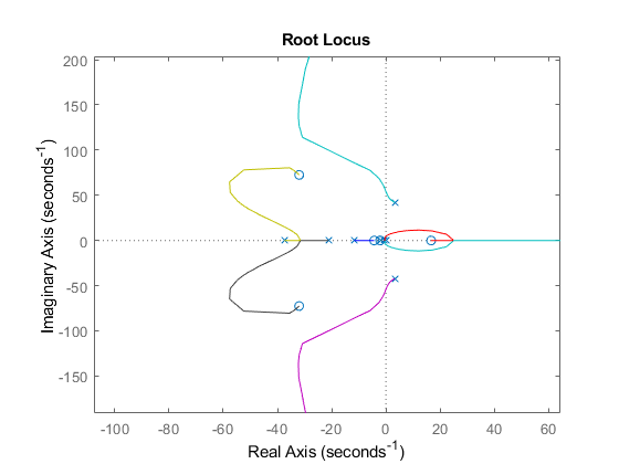
Looking at the root locus plot, however, shows me that if the unstable poles will move to the LHP with appropriate gain (the cyan and purple are the unstable poles):-

enter image description here

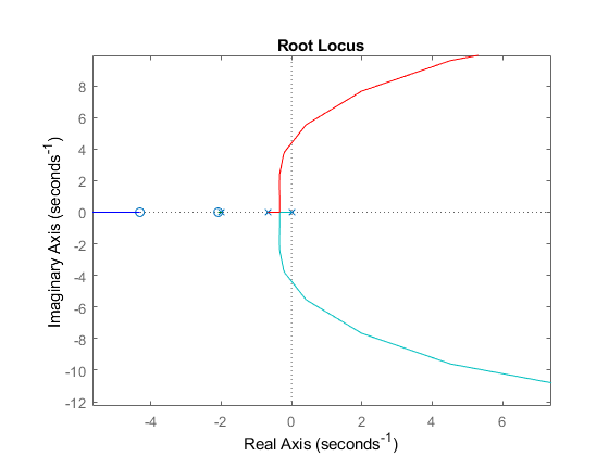
But the problem is, that if I add a gain high enough such that the unstable poles move to the left, then some of the poles in the LHP will move to the RHP in the process:-

enter image description here

Edit

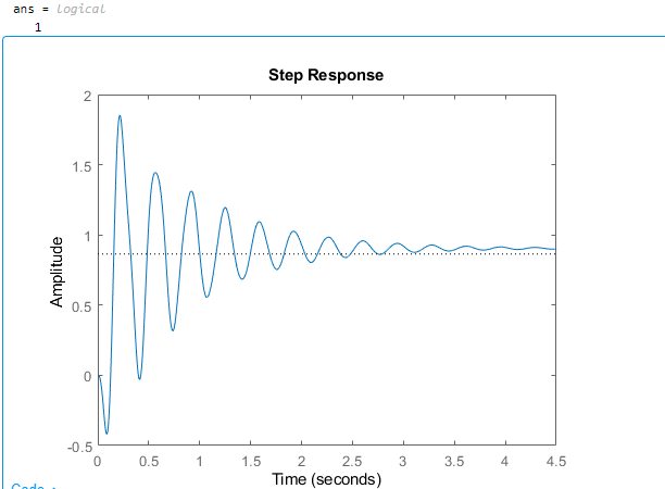
I made it stable! I added this term $G_d = \frac{s+0.002}{0.002s+1}$ and also a gain of $Kp = 1.6 $ to the forward branch. The closed loop step response with unity feedback looks like this (the 1 at the top indicates a stable system):-

enter image description here

The next step is just to remove the oscillations and improve settling time.

$\endgroup$
2
  • $\begingroup$ Have you tried PID controller ? Your RL indicates only about proportional close loop system, I would try to find a b and c such that a controller of the form (a/s +bs+c) would yield a proper result $\endgroup$
    – Ran Greidi
    Apr 25, 2021 at 10:52
  • $\begingroup$ Where is your RHP zero? If your RHP zero is slow, you might not be able to remove the oscillation. $\endgroup$
    – Ben
    Apr 25, 2021 at 14:25

1 Answer 1

1
$\begingroup$

The OP has a mistake in the numerator vector as there is an additional space between the minus sign and the 1.027e14 coefficient which will cause that to operate as an expression (-2.58e13 - 1.027e14) instead of negate the sign.

Had the system been correct, the resulting closed loop system with the compensator and gain chosen is underdamped. This can be resolved in this case by lowering the gain such that the closed loop poles are equidistant from the real and imaginary axis. Further details below.

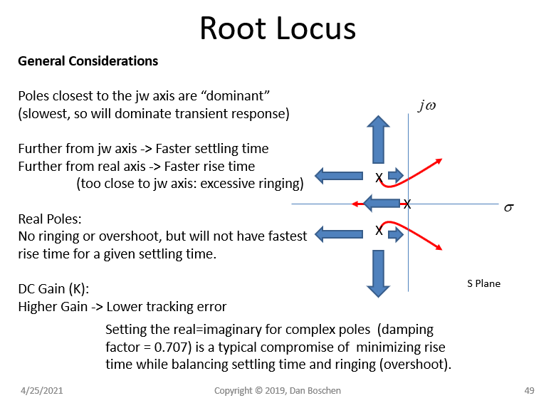
The resulting ringing is because the closed loop poles are too close to the $j\omega$ axis relative the the distance to the real axis, an underdamped system. The root locus shown by the OP shows all the possible closed loop pole locations depending on what loop gain is used, and thus as is with the current controller chosen the OP can lower the gain to select a condition with closed loop poles equidistant from both axis (which is an ideal trade of settling time and ringing). The general considerations for closed loop pole locations are summarized in the chart below.

root locus

$\endgroup$

Your Answer

By clicking “Post Your Answer”, you agree to our terms of service and acknowledge you have read our privacy policy.

Not the answer you're looking for? Browse other questions tagged or ask your own question.