1
$\begingroup$

I am trying to develop my understand of interpolation and signal reconstruction and uptill now i have understood that there are 3 commonly studied types of interpolation 1)Zero order hold interpolation 2)First order hold interpolation 3)Ideal interpolation

As far as i am able to understand,interpolation is processing of filling the empty sample space of sampled signal and zero order and first order tell us how samples are connected to each other.

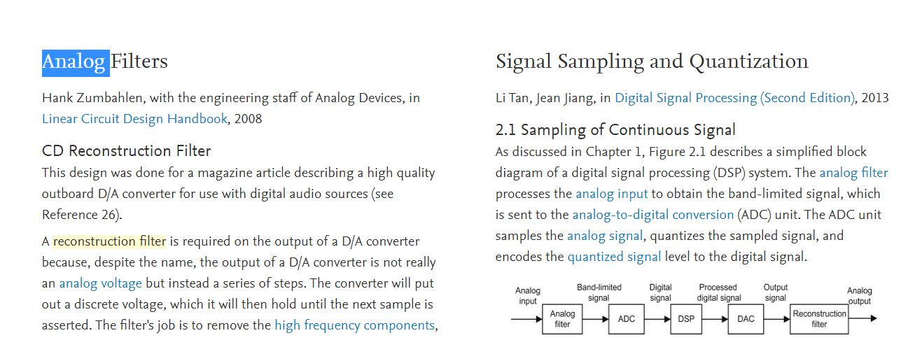
But still i have two main confusions: 1)What is meant by "order" here in interpolation?Is it referring to derivative?? 2)Many figures literature sources that i come across don't explicity contain block of interpolation,although some include block of low pass filter or reconstruction filter as shown in block diagram in attached snap of science direct page. In such scenario,how we can differentiate between low pass filter,reconstruction filter and interpolation filter(zero order hold or first order hold etc) enter image description here

$\endgroup$

2 Answers 2

1
$\begingroup$

First, the wiktionary definition of "interpolate", definitions 1 & 2, is spot-on here. Interpolation just means to fill in the blanks, correctly or not.

What is meant by "order" here in interpolation? Is it referring to derivative??

Dan's covered this -- it's the order of the polynomial you need to affect the reconstruction. I.e. if you're reconstructing $x_k$ into $x(t)$, then $x(t) = \sum_0^N a_n \left(t - T_s k\right)^n$, where $a_n$ is a function of the current $x_k$ and $N$ preceding ones. E.g. for a 0-order hold, $a_0 = x_k$, for a 1st-order hold $a_0 = x_{k-1}$ and $a_1 = \frac{x_k - x_{k-1}}{T_s}$, if I'm getting my math right, for a 2nd-order hold oh gosh I think I'll just look wise and say this is an exercise for the reader...

how we can differentiate between low pass filter, reconstruction filter and interpolation filter

This is one of those areas where there's no defined "right" term. I'm going to claim that an interpolation filter is a reconstruction filter (or, if you want to be strict about it, the set of all $n^{th}$-order holds is a subset of all reconstruction filters). And a reconstruction filter is usually a lowpass filter (but not always -- I'll touch on that).

If you have a system that has a digital to analog converter (DAC), and if that DAC acts like most DACs, then it takes on a new value when you write to it, and holds that value until you write another one. So as long as you're writing to it on a well-defined schedule, it acts like a zero-order hold.

So if there's a DAC, you can model it like a zero-order hold. If there's a DAC followed by a low-pass filter, then the combination of the implied zero-order hold in the DAC, and the low-pass filter, is your reconstruction filter.

(I used to work at a company that did digital processing on video, and pumped the result out on an analog composite video channel. In that case they used these clever low-pass filters that were 2nd- or 3rd-order LC filters that had a 1/sinc character up to some cutoff frequency, then fell off rapidly after that. This compensated for the fact that a zero-order hold has a sync(f) response, and gave nice reconstruction to the pixels).

If you have a system that takes a sampled-time system and resamples at a higher rate, then there may be no hold function at all -- the system may take the lower-rate samples and upsample and filter, or run them through a polyphase filter (basically, filter and upsample). In this case there's reconstruction, but again, no "hold" per se.

If there's a lowpass filter, then you can safely assume that its intent was for reconstruction (or some DSP beginner designed things, and just put it there out of desperation, achieving the same effect only more awkwardly).

And, finally, if you have a system that has a bandpass filter in there, at some frequency higher than Nyquist, then that's a perfectly valid reconstruction filter -- it's just reconstructing the signal from one of the alias frequencies of baseband, not from baseband itself.
$\endgroup$
0
$\begingroup$

Order refers to the order of the polynomial that is effectively used in the upsampling process. A zero-order hold will hold the previous value as a constant to insert all new interpolated samples, until the next sample, while a first-order interpolation will insert samples linearly between the existing samples, and so on.

Observe these two polynomial forms below using $m$ as the new higher rate samples and $n$ as the original lower rate samples, such that for $N$ original samples with $n = 0 \ldots N-1$ there are $M$ higher rate samples with $M=In$ from $m = 0 \ldots M-1$, where $I$ is the upsampling factor:

Zero order hold:

$$y[m] = y[n-1]$$

First order hold:

$$y[m] = y[n-1] + \frac{m-In}{I}(y[n]-y[n-1]) $$

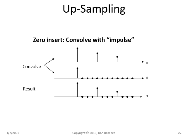
Often interpolation is done by upsampling by inserting zeros between the existing samples to have samples at the higher rate (and to be more complete in the mathematical forms above we would also operate on a zero-inserted signal at the higher rate to then show the two polynomial interpolations given with a consistent index of m), and this is followed by an interpolation filter which "grows" the zeros to the ideal (or close to ideal as limited by the filter design complexity) values for the interpolated signal.

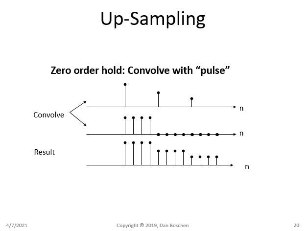
To see how this works, and the additional distortion that a zero-order hold approach would introduce (known as passband droop) please consider how a zero-order hold mathematically can be viewed as the convolution of our original signal with a (sampled) pulse as depicted in the figure below:

zero-order hold convolve with pulse

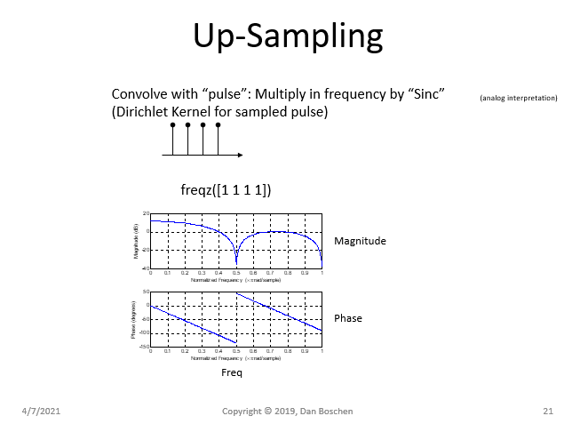
Convolution in the time domain is multiplication in the frequency domain. The Fourier Transform of a pulse is a Sinc function (and similarly the Discrete-Time Fourier Transform, DTFT, of a sampled pulse is the Dirichlet Kernel which is an aliased Sinc). This explains the "pass-band droop" distortion that a zero-hold upsampling would introduce as shown in the magnitude of the frequency response for the sampled pulse in the figure below (freqz is a Matlab/Octave/Python function which can produce the DTFT):

multiply with Sinc

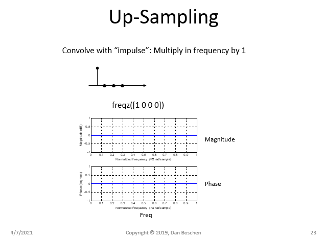
In contrast, a zero-insert approach would introduce no distortion within the passband of the signal (but replicates the spectrum in frequency which are removed with the interpolation filter):

up-sampling with zero insert

multiply by 1

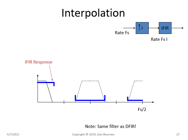
As further detailed in other posts, the upsampling process will introduce spectral images that must be filtered out to complete the interpolation process. The ideal interpolation filter (ideal is not realizable but can be approached at the expense of filter complexity and can be designed to comply with any distortion requirements). For example, below shows the new images (in dashed lines) that would be created from an upsampling by 4 (introduce 3 zeros in between each sample), and the desired response of a multi-band interpolation FIR filter (IFIR) that ideally would pass the pass band with no distortion, and completely reject the images.

Interpolation FIR

$\endgroup$

Your Answer

By clicking “Post Your Answer”, you agree to our terms of service and acknowledge you have read our privacy policy.

Not the answer you're looking for? Browse other questions tagged or ask your own question.