3
$\begingroup$

I have a high pass IIR filter with numerator

b = [0.997688673703782,-1.995377347407564,0.997688673703782];

and denominator

a = [1,-1.995372005171182,0.995382689643947];

the frequency response seems ok with fvtool(b, a). However, the response changes a lot after the coefficients are converted to fixed point numbers by

bb = round(b * 32768) / 32768;
aa = round(a * 32768) / 32768;

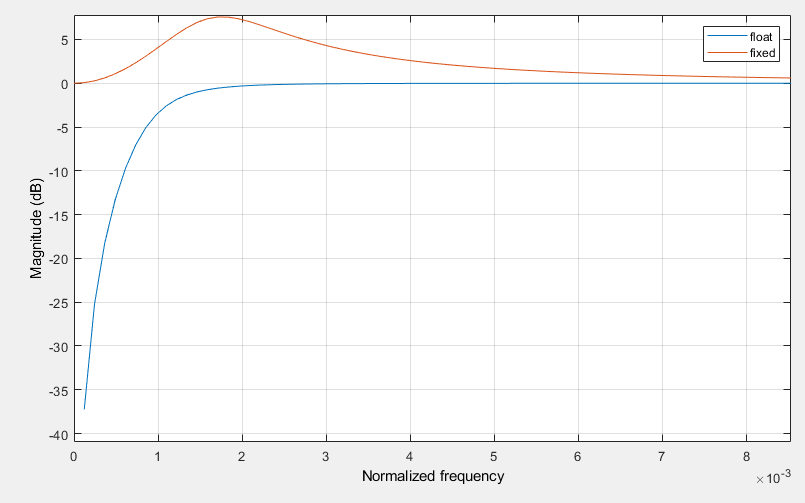
The frequency responses are as follows

enter image description here

How do I design a fixed-point digital filter with specific low frequency response? For example, a high pass filter with a desired cut off normalized frequency. Thx!

$\endgroup$
4
  • 1
    $\begingroup$ That's a DC blocking filter, not a low pass filter. $\endgroup$
    – Matt L.
    Commented Nov 20, 2020 at 11:54
  • $\begingroup$ how does this look if you replace each occurrence of 32768 with 8388608? $\endgroup$ Commented Nov 21, 2020 at 3:12
  • $\begingroup$ @MattL. sorry my mistake, that's a high pass filter. $\endgroup$
    – ZR Han
    Commented Nov 21, 2020 at 13:09
  • $\begingroup$ @robertbristow-johnson If I use 24-bit fixed point precision that would be fine. But is there any solutions with 16 bits? $\endgroup$
    – ZR Han
    Commented Nov 21, 2020 at 13:12

2 Answers 2

3
$\begingroup$

One problem with your design is that the quantized numerator coefficients don't add up to zero anymore, so you lose the desired notch at DC. That can be done differently, because even with quantized coefficients you can have a (double) zero at DC. Just make sure that $b[0]=b[2]$ and $b[1]=-2b[0]$.

The real problem is the denominator polynomial. It is well known that the available pole locations resulting from quantizing the polynomial coefficients are very sparse at low frequencies.

Note that the maximum magnitude of the ideal coefficients is close to $2$, so in order to quantize the coefficients to $16$ bits, you need to scale by $2^{14}$ instead of by $2^{15}$. This will result in the correct value range of the quantized integer coefficients:

bb = round( b * 2^14 ) * 2^(-14);
aa = round( a * 2^14 ) * 2^(-14);

The resulting quantized numerator coefficients guarantee a double zero at DC. However, the quantized denominator coefficients result in two real-valued poles, one of which is on the unit circle. I.e., there is a pole-zero cancellation and you end up with a first-order filter.

So one of the options you have is to use a first-order filter instead of a second-order filter. The numerator coefficients are trivial in this case:

b1 = [1,-1];

The denominator coefficient can be chosen experimentally using some negative value close to (but smaller in magnitude than) $-1$. Of course that value must be representable using $16$ bits:

a1 = [1, round( -r * 2^(15) ) * 2^(-15)];

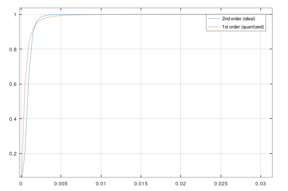
The plot below shows the frequency response of the ideal second-order filter (blue) and of the quantized first-order filter with $r=0.998$. You have to judge for yourself if the deviation from the ideal response is tolerable for you application or not.
enter image description here

Another solution is to use a different filter structure which is more robust to coefficient quantization (at least at low frequencies). Such a structure is the coupled-form structure, which is described in most textbooks on DSP (e.g., in Oppenheim's Discrete-Time Signal Processing).

$\endgroup$
3
  • $\begingroup$ Yes, 1st order sections give better match. Here's an example : fs = 44100; fc = 24; %% BLT w0 = 2.0 * pi * fc/fs; b0 = cos(w0) + 1; b1 = -(cos(w0) + 1); a0 = cos(w0) + sin(w0) + 1; a1 = sin(w0) - cos(w0) - 1; a0 = round(a0 * 32768) / 32768; a1 = round(a1 * 32768) / 32768; b0 = round(b0 * 32768) / 32768; b1 = round(b1 * 32768) / 32768; %a0 = 2.003417968750000 %a1 = -1.996582031250000 %b0 = 2 %b1 = -2 % a = [a0 a1]; b = [b0 b1]; HP1=tf(b, a, 1/fs); [mag, phase] = bode(HP1^2,2*pi*nf); ... $\endgroup$
    – Juha P
    Commented Nov 21, 2020 at 15:03
  • $\begingroup$ Forgot the nf definition in above code which is: nf = logspace(0, 5, fs/2); $\endgroup$
    – Juha P
    Commented Nov 21, 2020 at 15:10
  • 1
    $\begingroup$ Thank you Matt. Finally I decide to use a first-order filter, which meets my need. And another two answers from you are quite good. 3 dB cut-off frequency of first-order IIR high-pass filter and Single-pole IIR low-pass filter - which is the correct formula for the decay coefficient? $\endgroup$
    – ZR Han
    Commented Nov 23, 2020 at 2:57
2
$\begingroup$

This filter amounts to a cutoff frequency of 24 Hz @ 44.1 kHz. That means your poles are extremely close to the unit circle so you require way more numerical precision than you can get with 16 bits.

You need more resolution: even 24 bits are iffy for that low a cutoff frequency, but 32-bit should do nicely. This also depends on your requirements: how much noise can you tolerate and what is the minimum attenuation you need ?

Fixed point processing is mathematically quite challenging especially if the poles get anywhere near the unit circle. It requires detailed numerical analysis of each filter stage and careful management of overhead, stage ordering, state variable scaling, clipping, rounding, noise floor, etc.

$\endgroup$
3
  • $\begingroup$ it doesn't quite sufficiently address the difference between the red and blue curves. the quantized coefficients should still have been a HPF (or DC blocking filter). now, because of magnitudes close to 2, the quantized coefficients are bigger than 16-bit. they are 17-bit. now i dunno what the OP was using to compute and graph frequency response, but if it used actual 16-bit integers, he has an overflow problem but if the OP is sending the aa and bb to the same freqz(), then there should be relatively little trouble. the quantized poles and zeros aren't far off. $\endgroup$ Commented Nov 21, 2020 at 3:06
  • $\begingroup$ Thanks Hilmar. Is there any other way besides increasing quantization accuracy? Such as multirate methods. If I downsample the input signal to a half, a quarter or even lower sample rate, what do you think of the performance of 16 bits? $\endgroup$
    – ZR Han
    Commented Nov 21, 2020 at 13:27
  • $\begingroup$ Your options depend on your requirements. What SNR do you need, how much attenuation do you need at what frequency? Where does your pass band start and how flat does your passband need to be? $\endgroup$
    – Hilmar
    Commented Nov 21, 2020 at 15:31

Your Answer

By clicking “Post Your Answer”, you agree to our terms of service and acknowledge you have read our privacy policy.

Not the answer you're looking for? Browse other questions tagged or ask your own question.