1
$\begingroup$

What are the different types of interpolation used in DSP for reconstruction of analog signal from discrete/digital signal

I am able to somehow learn two types of interpolation 1st is "zero order hold interpolation"and 2nd is "linear interpolation(first order interpolation)"

Reconstructed output looks like stair case or square wave for zero order hold interpolation while reconstructed output for linear interpolation(1st order interpolation) looks like a triangular wave

There are other types of interpolation besides above?

What are those types? (That types give a much better/smoother reconstructed signal as compared to two types i discussed above)

What is the order of polynomial in those types (just like "zero order hold" type had zero order and "linear interpolation" type had order one)

For those other types of interpolation, what/how are the appearances/looks of reconstructed output waves ? (Please kindly try to include those wave graphs in your answer)

By reconstruction, i mean conversion of digital into analog signal

$\endgroup$
5
  • $\begingroup$ do you mean the actual hardware that reconstructs a continuous-time analog signal from the digital samples? that device is called a Digital-to-Analog Converter or DAC or D/A. but if you wanna know the math that does interpolation, so that you can do it completely in the digital realm, that's what zero-order hold or linear interpolation or polynomial interpolation or even $\operatorname{sinc}(\cdot)$ interpolation is about. is it the latter? $\endgroup$ Commented Apr 8, 2020 at 19:00
  • $\begingroup$ Or perhaps you're talking about reconstruction filters? Could you please edit your question with an example of what you're trying to actually do. Because there's a lot of stuff in DSP that can be called "reconstruction". $\endgroup$
    – TimWescott
    Commented Apr 8, 2020 at 19:05
  • $\begingroup$ @robert bristow Johnson. Yes i am talking about the math that does the interpolation, please kindly update your answer so as to also include description/explanation and wave/graph of polynomial interpolation and interpolation. You have already explained and drawn graph of zero order and linear interpolation $\endgroup$
    – DSP_CS
    Commented Apr 9, 2020 at 7:02
  • $\begingroup$ @TimWescott , i have updated my question and by reconstruction i mean i am trying to convert my sampled/discrete signal back to continuous/analog signal $\endgroup$
    – DSP_CS
    Commented Apr 9, 2020 at 7:10
  • $\begingroup$ I'm sorry, it's still not clear. You're laying out options that you might see in a signal processing course, yet your use of "analog" implies that you might want something that is actually used in the real world -- which is it? Typically a real-world system uses a DAC followed by a reconstruction filter, or it drives a class-D amplifier followed by a power filter. A DAC can be modeled as a zero-order hold, but isn't, quite. A class-D amplifier isn't a linear system, so it's part of "more in this world that doesn't fit into your philosophies" when you're taking an introductory DSP class. $\endgroup$
    – TimWescott
    Commented Apr 9, 2020 at 14:54

2 Answers 2

4
$\begingroup$

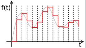
Zero-order hold will result in a piecewise-constant waveform.

enter image description here

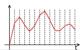
Linear interpolation will result in a piecewise-linear waveform.

enter image description here

If you want a piecewise-quadratic or piecewise-cubic or higher order polynomial interpolation, it will not appear much different from the original bandlimited waveform.

$\endgroup$
1
  • $\begingroup$ Yes i am talking about the math that does the interpolation, please kindly update your answer so as to also include description/explanation and wave/graph of polynomial interpolation and interpolation. You have already explained and drawn graph of zero order and linear interpolation $\endgroup$
    – DSP_CS
    Commented Apr 9, 2020 at 7:03
2
$\begingroup$

As Robert said, there are other interpolations that get very close to the original bandlimited waveform. The ideal is the Whittaker-Shannon interpolation formula, or sinc interpolation. This is equivalent to convolution of the signal data with a sinc function, the impulse response of an ideal lowpass filter, at half the sample rate.

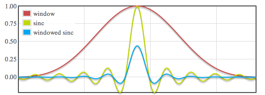
But the sinc function is infinite, so we truncate the response on both sides of the central lobe, and window it to fade the abrupt discontinuity and improve behavior. The result is also a lowpass filter, also linear phase, but with a more gradual cutoff slope (transition band), and an imperfect stop band. As such, we move the cutoff frequency down below half the sample rate in order to get sufficient attenuation for antialiasing.

A Kaiser window is a good choice for the window. It’s easy to calculate, and easy to adjust for stop band attenuation.

Your choices will be the sinc frequency (filter corner frequency), its length (how many points to take into account in the interpolation, which will determine the filter’s steepness, or transition-band width), and the window (determining tradeoff of transition-band width and stop-band attenuation).

Here’s a graph of a truncated sinc function and a Kaiser window, with the resulting product, the windowed-sinc function (in this case the function has been scaled for use as an upsampling filter, which also keeps it from obscuring the sinc function).
enter image description here

Here's the frequency response of such a filter, in this case being used for 2x sample rate conversion, with the filter cutoff at half the original sample rate, showing the gradual transition and limited stop-band attenuation resulting from the finite impulse response of the windowed sinc:

enter image description here

You can find a windowed sinc calculator here: https://www.earlevel.com/main/2010/12/05/building-a-windowed-sinc-filter/

Also, because the sinc function is smooth, you can pre-compute an oversampled windowed-sinc table and interpolate linearly between its points for an efficient way to calculate an arbitrary point between samples—because an oversampled sinc, like a heavily sampled sine wave, it relatively smooth, linear interpolation between points can have low error.

To answer the question of what the waveform would look like, it would look like the bandlimited input waveform that you sampled. The longer the sinc, the closer to the original. Since shorter impulses repsonses will give less perfect and steep lowpass filtering, so they will deviate slightly from the original, but the interpolation will be formed from the sinc curves, they will not be formed with the straight lines of zero order hold and linear interpolation.

Semantic note: I'd say the windowed sinc filter is what people often think of pairing with the word "reconstruction", but "interpolation" can be more general. That is, few people would say a linear interpolator is a reconstruction filter, because its output deviates too much from what we'd expect for reconstruction, but it's certainly a valid interpolator within its limitations. There are other interpolators suitable for reconstruction, but a sinc filter descends directly from the ideal, so I think is more typically associated with "reconstruction".

$\endgroup$

Your Answer

By clicking “Post Your Answer”, you agree to our terms of service and acknowledge you have read our privacy policy.

Not the answer you're looking for? Browse other questions tagged or ask your own question.