3
$\begingroup$

I have been further reading up on carrier recovery methods and something is not clear to me:

It's written that a carrier frequency offset results in a rotating constellation diagram but if you are sampling at the output of a correlator such as RRC it's not clear to my why this is the case.

For an all digital receiver, the ADC samples will be rotated prior to going into the correlator but it appears the correlation process in conjunction with the frequency offset will do more than rotate the constellation diagram.

Am I wrong?

$\endgroup$
4
  • $\begingroup$ I can't provide a complete answer right now, but if you work out the math you'll see that the MF output has terms $\cos(\theta)$ and $\sin(\theta)$, which result in the output point to be rotated $\theta$ rads, where $\theta$ is the carrier phase offset. $\endgroup$
    – MBaz
    Commented Sep 3, 2018 at 17:42
  • $\begingroup$ Hmmm, when I was looking at it the matched filter requires an integration where a sine/cosine is within the integral. I wasn't sure how to actually do anything with that. I would love to see a more indepth answer when you get a chance as I am missing something. $\endgroup$ Commented Sep 3, 2018 at 17:50
  • 1
    $\begingroup$ The rotating constellation diagram is with respect to the fixed axes of $\cos(\omega t)$ and $-\sin(\omega t)$ with respect to which the RRC correlator is defined. Thus, the correlator output is rotated with respect to the axes, and furthermore each successive symbol generally has a different rotation with respect to the axes because of the frequency offset. $\endgroup$ Commented Sep 3, 2018 at 19:50
  • $\begingroup$ Hmm, I was thinking you could approximate the rotation as being fixed across the symbol interval and take it to be what it would be at the center of the RRC pulse but that isn't a completely accurate account of what's happening. If you actually write out the correlation sum where each sample is rotated a little bit for the I and Q components I'm not seeing how the resulting complex number will only have a rotation associated with it. $\endgroup$ Commented Sep 3, 2018 at 20:45

3 Answers 3

4
$\begingroup$

In the frequency domain a signal with a carrier offset looks like the following-

Signal with carrier offset

This is usually modeled as the desired baseband signal convolved (in the frequency domain) with a complex tone with frequency equal to the carrier offset.

Decomposed signal with carrier offset

As you are probably already aware, convolution in the frequency domain is equivalent to multiplication in the time domain. Thus, the baseband signal is multiplied, sample by sample, by the complex tone in the time domain. As the complex tone is rotating around the complex plane, at a speed that is proportional to its frequency, this causes the baseband signal to rotate as well. We can see that when we recognize that multiplication of polar values causes the phases to add, so the tone's phase is added to the baseband signal's, which causes the rotation.

So, given that, does the output of the symbol matched filter also rotate? Yes.

Let's look at a simple example: BPSK with the symbol being a simple +1 and an initial phase offset of 0.
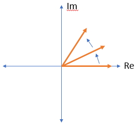
Rotating signal

Although the signal starts at 0 phase, each sample rotates it farther and farther around the complex plane. Your main question seems to be about what happens when the symbol matched filter is applied, and you bring up the raised root cosine (RRC) filter in particular. The RRC filter is just a weighted boxcar filter. It sums up sequential samples after a weight has been applied to each. For ease of drawing, let's assume an RRC filter that only has three taps. The middle tap will be the biggest, with the edges being smaller.
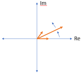
Samples after RRC filter is applied

Hopefully it is obvious that the angle of the sum of these weighted samples/vectors will not be 0. Now picture the next three samples. They will be rotated even more than the first three, and the weighted sum of them will also be rotated more. This does, of course, continue.

At this point it is hopefully clear that the matched filter does not prevent rotation, it just averages it.

$\endgroup$
2
  • $\begingroup$ Thanks for the explanation, my issue though is that I don't think the total output magnitude of the matched filters(using the definition of complex magnitude) will be constant in length. I think the rotation operation will result in some reduction in the total magnitude of the symbol also. The reason(like you said) is that each tick the complex number is rotated a little more. The sum won't end up being the same. $\endgroup$ Commented Sep 4, 2018 at 22:07
  • $\begingroup$ That's correct, it won't be the same. With no rotation it's 100% constructive interference, no destructive interference. With the rotation there is some destructive interference- the faster the rotation and the longer the filter, the more destructive interference you'll get. $\endgroup$
    – Jim Clay
    Commented Sep 4, 2018 at 22:55
4
$\begingroup$

The correlator is just a filtering operation. So in the case of passband pulse-amplitude modulation (PAM), such as QPSK or QAM, the (noiseless) received analytic signal before demodulation and sampling can be written as

$$r(t)=e^{j((\omega_c+\Delta\omega) t+\phi))}\sum_{k}A_kp(t-kT)\tag{1}$$

where $\Delta\omega$ is a frequency offset, $\phi$ is a phase offset, $\omega_c$ is the carrier frequency as estimated by the receiver, $A_k$ are the complex data symbols, and $T$ is the symbol period. The pulse $p(t)$ represents the combination of the transmit filter, linear distortions on the channel, and the receive filter (correlator).

Demodulation with $e^{-j\omega_ct}$ and sampling at the symbol rate $1/T$ gives

$$\tilde{r}[n]=e^{j(\Delta\omega nT +\phi)}\sum_kA_kp((n-k)T)\tag{2}$$

If for simplicity we assume that the combined pulse $p(t)$ satisfies the Nyquist criterion $p(kT)=\delta[k]$ (i.e., there is no inter-symbol interference), then $(2)$ simplifies to

$$\tilde{r}[n]=e^{j(\Delta\omega nT +\phi)}A_n\tag{3}$$

which should make it clear that at time $t=nT$ the received symbol is a rotated version of the original symbol, where the rotation has a constant component $\phi$ (the phase offset), and a time-dependent component $\Delta\omega nT$ caused by the frequency offset. Consequently, if $\Delta\omega\neq 0$, the constellation rotates.

$\endgroup$
2
  • $\begingroup$ Thanks, I am still confused though as the correlator uses multiple samples of the signal and this sampled signal is altered by the frequency offset(at least in the case of an SDR). I don't understand how you were able to apply the correlator before extracting the frequency offset. $\endgroup$ Commented Sep 3, 2018 at 20:42
  • $\begingroup$ @FourierFlux: Maybe you could edit your question to make the source of your confusion a bit clearer (using some math?); I'm not sure I understand what exactly it is that you don't understand. $\endgroup$
    – Matt L.
    Commented Sep 4, 2018 at 12:57
2
$\begingroup$

The original post mentions : "I have been further reading up on carrier recovery methods".

Just for clarification - even though this thread is a few years old - did you mean symbol recovery methods instead of 'carrier recovery' methods?

The original post also mentions: "It's written that a carrier frequency offset results in a rotating constellation diagram but if you are sampling at the output of a correlator such as RRC it's not clear to my why this is the case."

Here - we need to make some assumptions - such as the incoming waveform is a quadrature waveform (eg. QAM) with sinusoidal carriers --- in-phase carrier and quadrature carrier. And also assume an ideal communications channel.

If down-conversion is done, and if the receiver oscillator is at a slightly different frequency (relative to the transmitter oscillator), then the time-domain output of the down-converter will be a waveform that contains versions of the transmitter-side QAM symbols (or 'vectors'), except those vectors (at the receiver side) will be rotating. How much the vector rotates (per some amount of time) depends on how different the frequencies are between transmitter and receiver. Also, the direction (clockwise or counter-clockwise) of rotation will depend on whether the receiver oscillator frequency is higher or lower than the transmitter's oscillator frequency.

So - what is (or was) written regarding vector rotation when carrier frequency offset exists - is true (at the output of the down-converter). But - if you refer to some point further down-stream - such as after frequency offset correction or compensation or removal techniques are applied, then that's a view from a different point.

$\endgroup$

Your Answer

By clicking “Post Your Answer”, you agree to our terms of service and acknowledge you have read our privacy policy.

Not the answer you're looking for? Browse other questions tagged or ask your own question.