0
$\begingroup$

Goal: Obtain the 3-axis accelerations from the Bosch BMI160 IMU when measuring the accelerations of the bogie of a commercial train. The accelerometer used is installed in a PCB and used by an mbed microcontroller. The mbed manages to receive and save the data from the accelerometer at 50 Hz. The BMI160 has some options such as measurement range that can be changed: to avoid sensor saturation the limit is set to ±4g.

Issue: The Z-acceleration (gravity-like oriented) shows an important bias due to unknown reasons. Phenomenon in Figure 1 and 2:
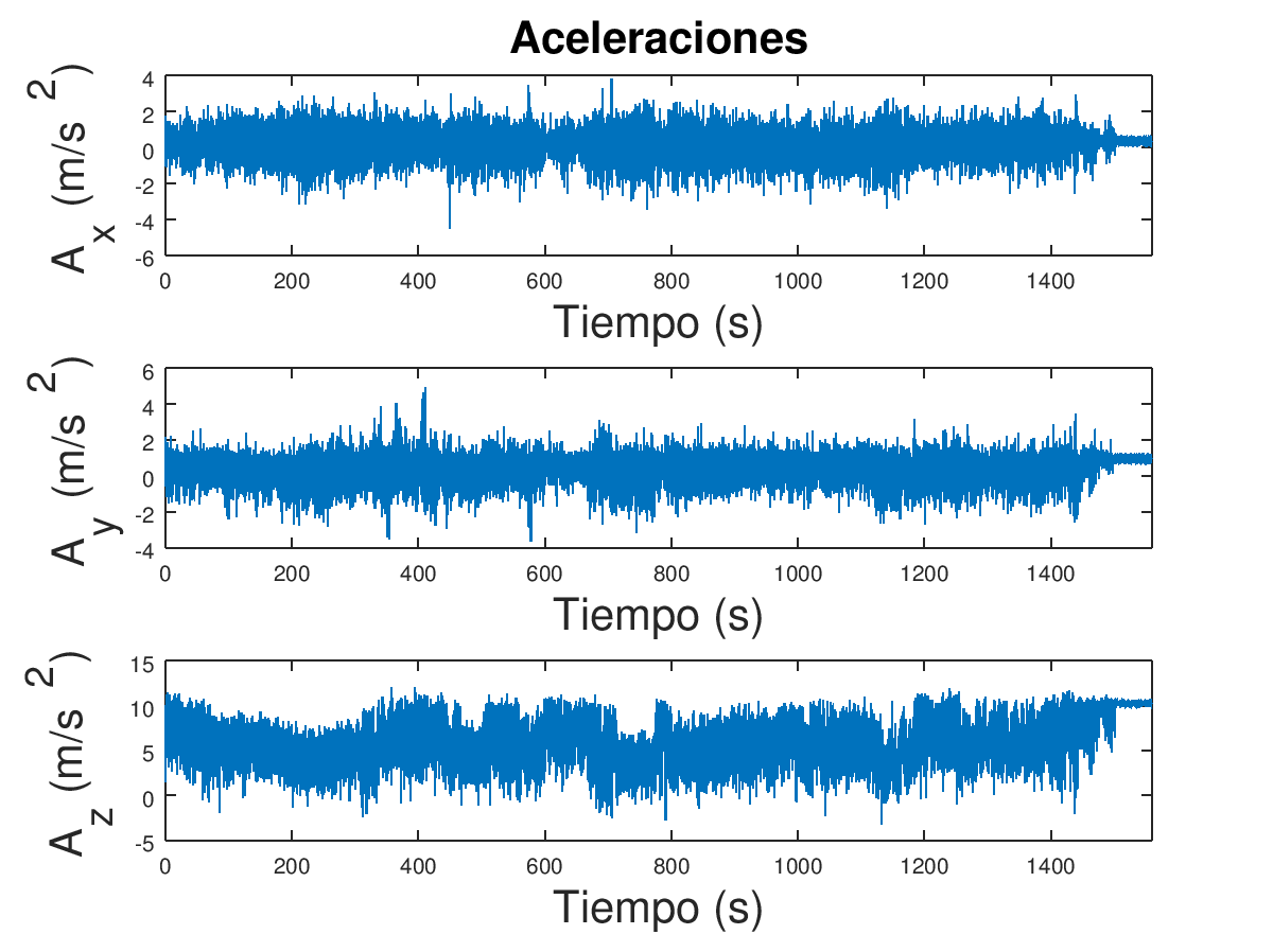
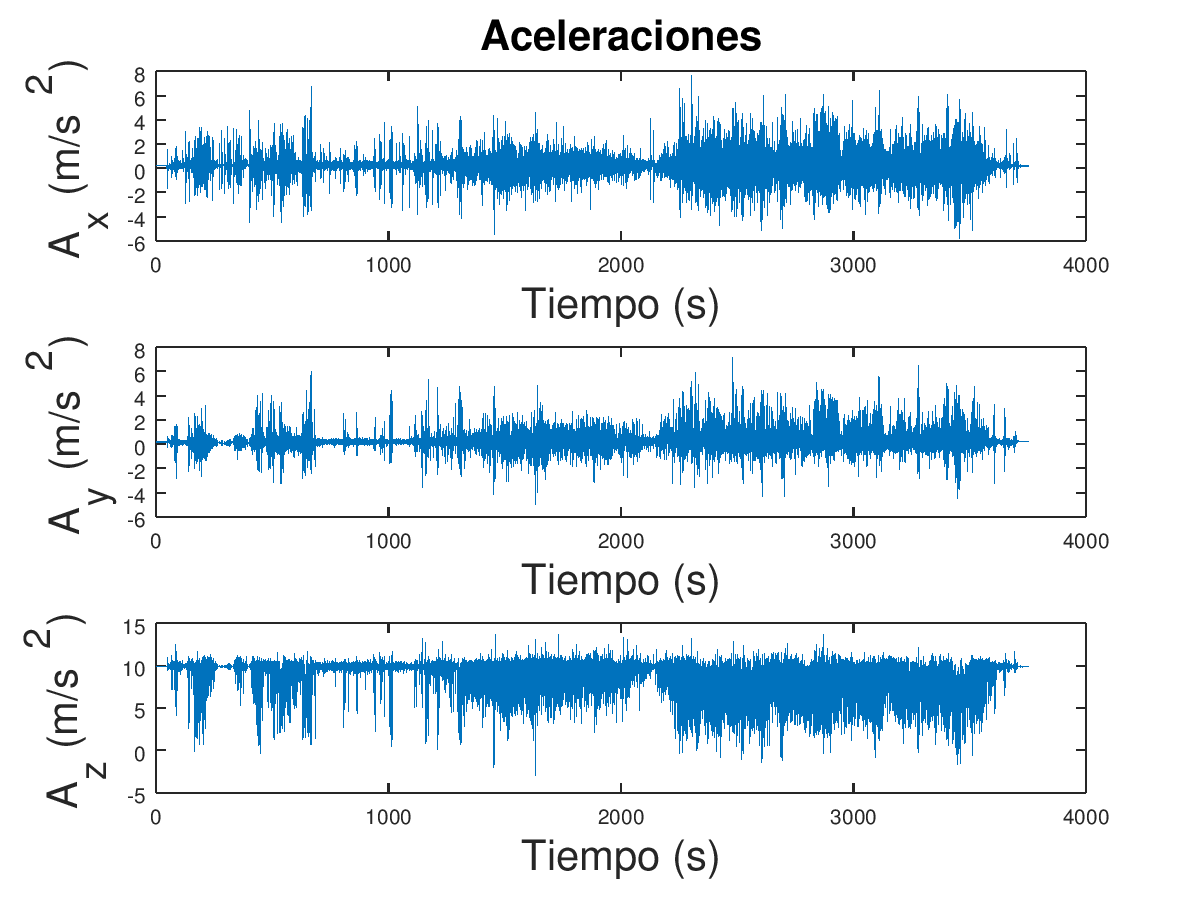
Figure 1

Figure 2

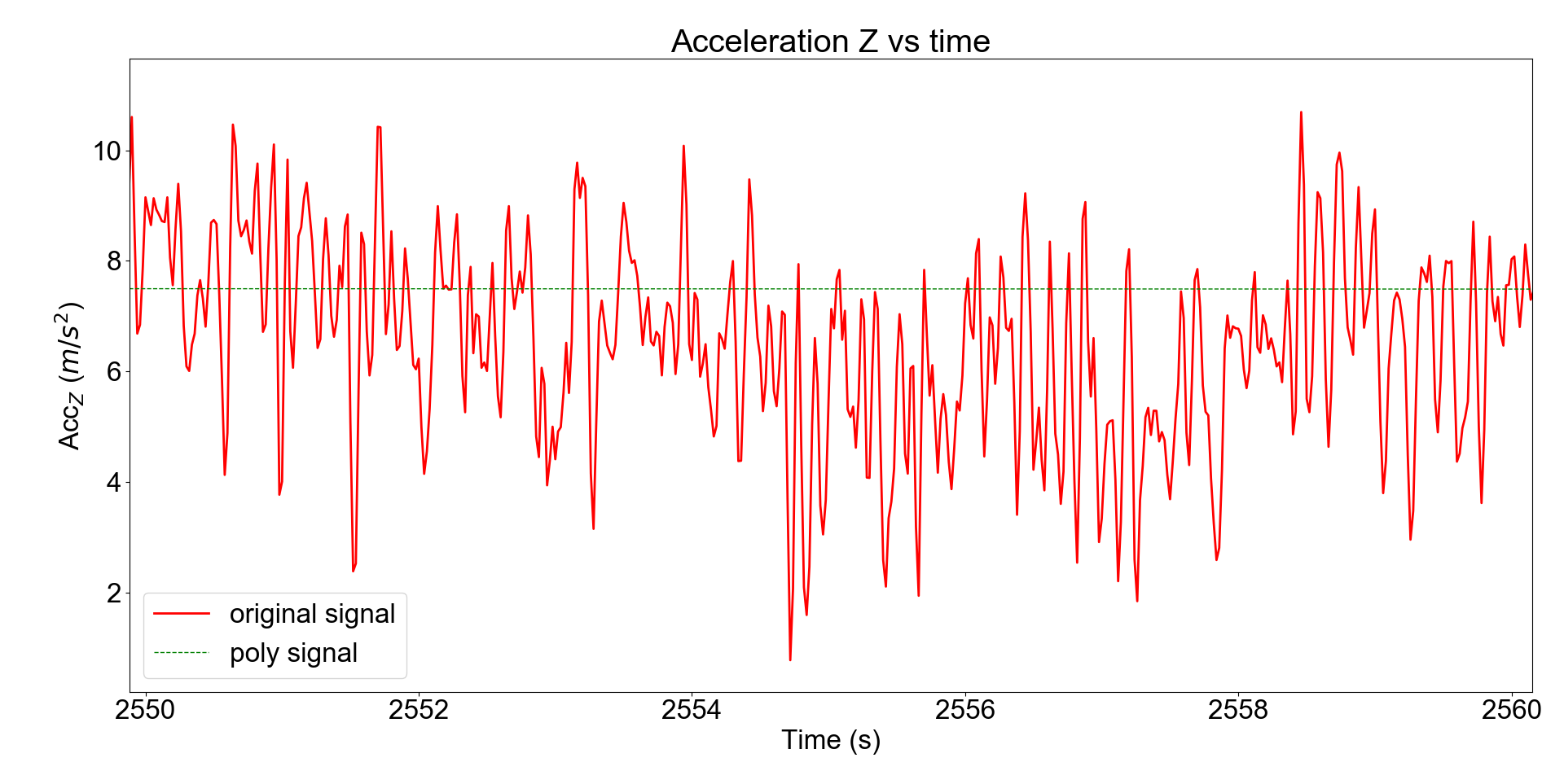
The odd phenomenon can be more easily seen in this picture of the zoom Z-acceleration:

Figure 2.zoom

Figure 2.zoomzoom

time stamps and $ Acc_z $ data can be found here: https://pastebin.com/raw/4PyAtVU8

It can be seen on it, that the average of that signal is not the gravity value. If it where due to the rotation of the object, a similar effect shall be seen in the other axis. Anyway, this does not seem to be the case, as the vehicle is a railway going forward.

If we calculate the low-pass-filtered signal ($ f_cut = 0.1\ Hz $), the signal is clearly non-oscillating. The expected result should be something more similar to what is shown in purple in the next figure:
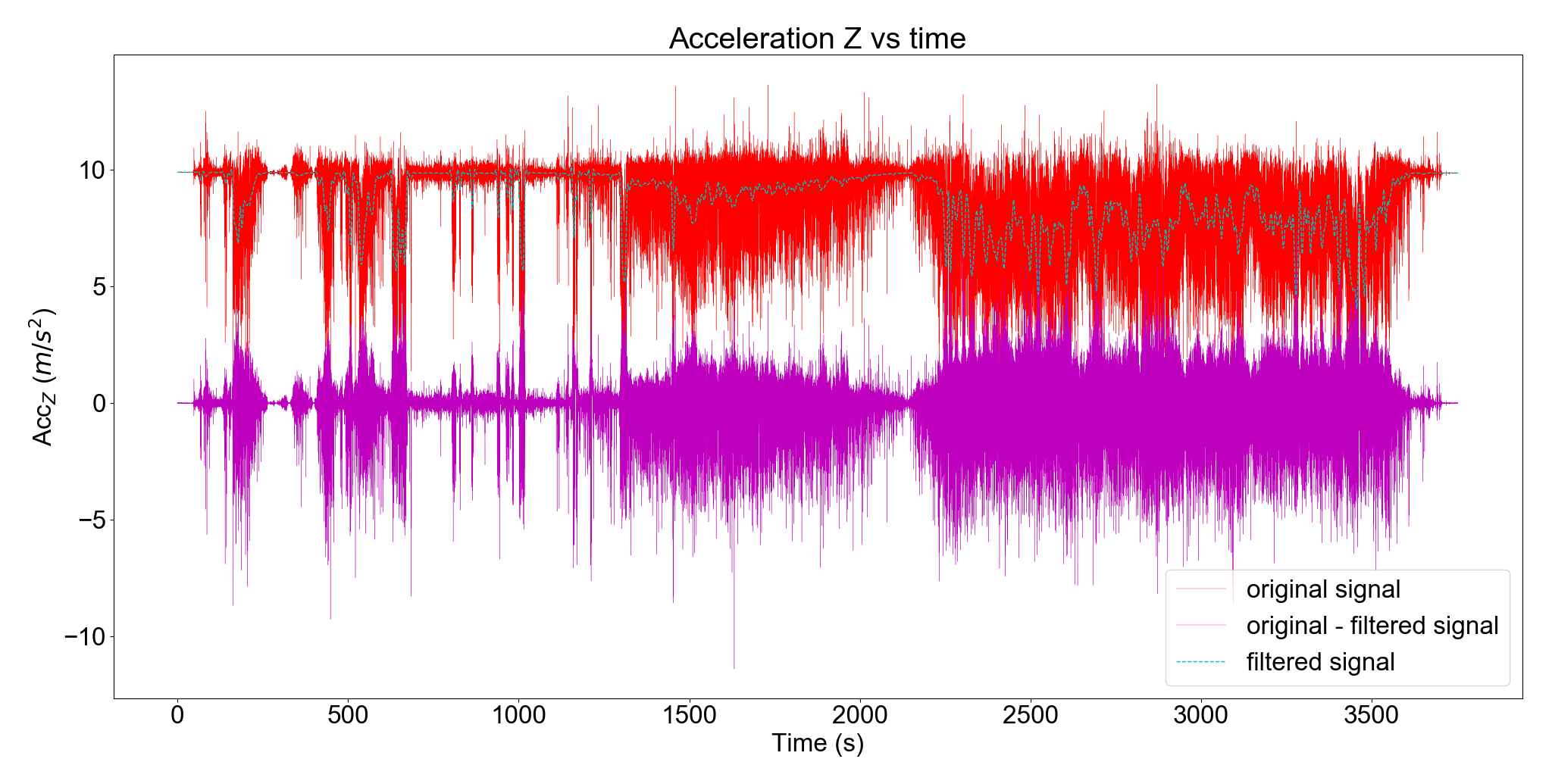
Filtered signal

Moreover, if we zoom in the last part of the signal, we can see that there are not any particular trends:
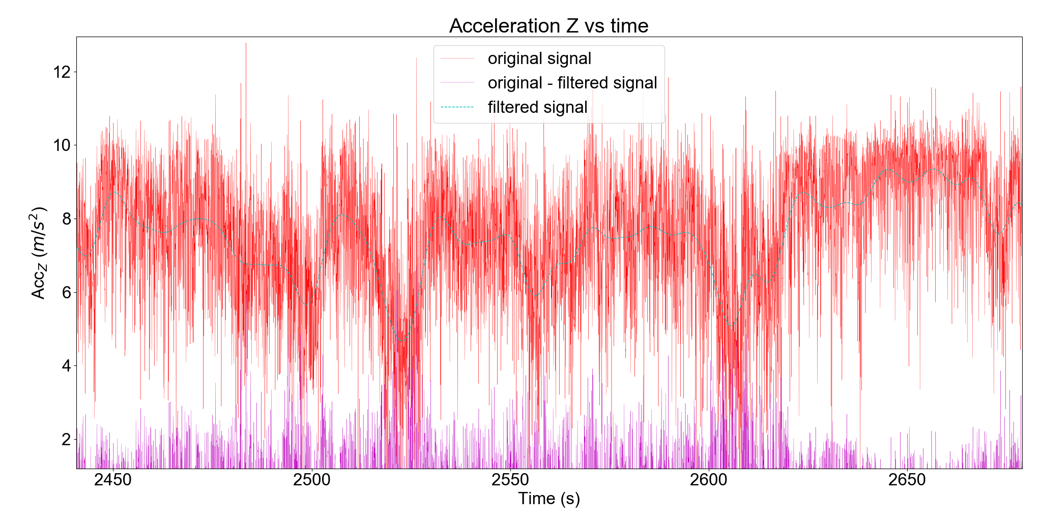
Filtered signal zoomed

Question: Why the bias of the acceleration, which should be a slow-changing as a random variable, causes such a distorsion on the signal? It seems to affect only to big accelerations caused by impacts.

In next figure, you can see more information about the device layout:
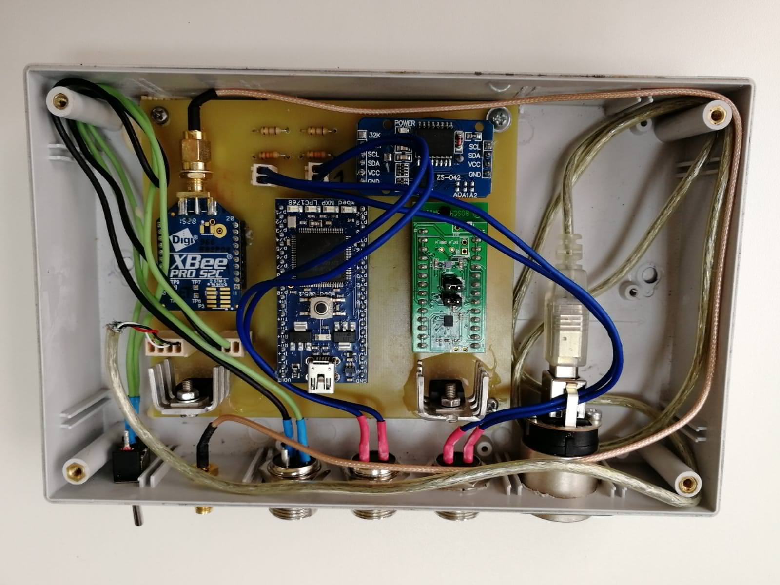
Layout

The accelerometer (green component) is well fixed to the PCB with strong adhesives. The PCB itself is screwed to some wooden pieces which are also strongly sticked to the plastic box.

The whole device is fixed to the train through duck tape using metal plates for the contact. All componentes are strongly fixed one to each other and we have not observed any relative bouncing between components. The next figure shows the set up:
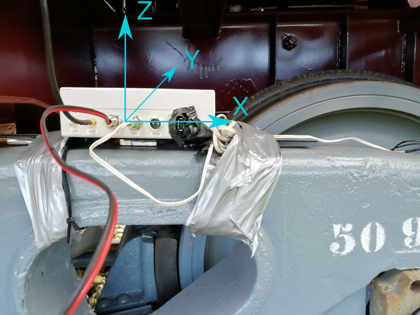
Vehicle axis

The blue axis are the vehicle reference system and, as it can be stated with the sign of gravity value, it does not coincide with the accelerometer axis.

I think the phenomenon may be due to an aliasing issue or just a problem with this low-cost accelerometer. Any insight from anybody?

$\endgroup$
12
  • $\begingroup$ Can you please update this post by adding a figure where you mark clearly which feature of the waveforms you find "odd"? It does not have to be perfect, even if it is free-hand marked in Paint it will work. The point is to note exactly what you perceive as "odd" here. I would lean more towards what Peter K. is telling you, especially about the clipping. Are you interfacing to the Accelerometer directly or is it inside a device? Can you check if it does some sort of internal limiting or put it in a mode that it gives you "raw" data directly? $\endgroup$
    – A_A
    Commented Apr 24, 2018 at 15:38
  • $\begingroup$ @A_A Thank you for yor comments. I added the graph with the phenomenon marked and also added some more context. The accelerometer used is installed in a PCB and used by an mbed microcontroller. The mbed manages to receive and save the data from the accelerometer at 50 Hz. The BMI160 has some options such as measurement range that can be changed: to avoid sensor saturation the limit is set to ±4g. $\endgroup$
    – Gaussiano
    Commented Apr 24, 2018 at 16:11
  • $\begingroup$ Thank you, can I please ask how is the accelerometer mounted on its board? Is it a PCB inside a box? Is the PCB screwed on at least 3 points across its entire length of is the PCB sort of dangling? When the accelerometer is mounted on the vehicle, how is it coupled to it? In other words, are we sure that these readings don't come from some sort of mechanical reason? And since this "oddity" is both present when the system is mounted on the vehicle and when you excite it, it might be something to do with the construction of the housing (?) $\endgroup$
    – A_A
    Commented Apr 24, 2018 at 19:10
  • $\begingroup$ @A_A Added more information about the set-up and layout. The pcb is screwed to 4 pieces of wood which are glued to the plastic box. The coupling to the vehicle was through duck tape and should be no bouncing between components. Apart from that, we are not sure this is not due to mechanical reasons, but we are firstly removing electronic explanations such as aliasing, saturation, or who-knows. $\endgroup$
    – Gaussiano
    Commented Apr 25, 2018 at 10:40
  • $\begingroup$ Thank you very much, this is definitely more than I asked for :) No, aliasing will not manifest itself in this way and in any case, the accellerometer has onboard processing to avoid this. Maybe this is from the bogie suspension which definitely has more travel in one direction but not the other. So, it may be compressing the springs downwards but trying to flex the bogie chassis upwards if it is not loaded. Were you knocking the box in place or on a table? It looks like a non-linear mode gets excited. Can you zoom in on that part so that we see what's happening? Pastebin data segment? $\endgroup$
    – A_A
    Commented Apr 25, 2018 at 12:12

2 Answers 2

1
$\begingroup$

the problem is asymmetric railing. It only occurs on the Z-axis because it is affected by gravity, when the vibration exceeds the accelerometer's range the asymmetric range causes a bias. When the vehicle is in motion vibration occurs. Solution would be with improved mechanical mounting or artificially clipping the data. See link below:

https://www.analog.com/en/technical-articles/vibration-rectification-in-mems-accelerometers.html

$\endgroup$
1
  • $\begingroup$ Wow, thank you very much! You really identified this phenomenon to me. I can know start to work on it! $\endgroup$
    – Gaussiano
    Commented Jun 18, 2019 at 6:51
0
$\begingroup$

The Earth gives you an acceleration of $ g = 9.8 \mbox{m/s}^2$ in the $z$ direction. That is what the accelerometer is measuring.

$\endgroup$
5
  • $\begingroup$ Thank you for the comment. I know that is the value of the gravity, but I would like you to focus on the strange movement that signal does. As the vehicle does not fly up and down, the Z-axis magnitude should be oscillating around zero and it is not the case, as there are some sections in which the signal shows non-zero mean. Moreover, in the many sections you can see the acceleration signal going more down than up, what is disturbing at the least. $\endgroup$
    – Gaussiano
    Commented Apr 24, 2018 at 14:12
  • $\begingroup$ @Gaussiano If the accelerometer is on Earth, then the Z-axis magnitude should be oscillating around 9.8 $\mbox{m/s}^2$, which it is. If your object is moving (and being accelerated), then one would expect the acceleration signal to go up an down. Why is it disturbing? For what it's worth, it looks like the bottom plot is clipping around $t=40s$, which might be what you're disturbed by? $\endgroup$
    – Peter K.
    Commented Apr 24, 2018 at 14:16
  • $\begingroup$ As you stated, the signal must be oscilating around $ 9.8\ m/s^2 $ so the mean must be that value. The problem is that the mean of the signal does not remain at $ 9.8 $ but it slowly changes throught the measurment. Before I said zero-mean incorrectly, as I meant 9.8-mean. Apart from that, it is true that the sensor is saturating at $ t = 40\ s $ what makes the figure a bad example (I will remove it). $\endgroup$
    – Gaussiano
    Commented Apr 24, 2018 at 14:31
  • $\begingroup$ If you focus on the last part of the Figure 2 in the Z-axis you can see this: !Figure 2. Zoomed And that makes clear that it is not oscillating around $ 9.8\ m/s^2 $. That is the phenomenom I want to understand. Would it be due to the real acceleration of the vehicle? Is it for anything else? $\endgroup$
    – Gaussiano
    Commented Apr 24, 2018 at 14:37
  • 2
    $\begingroup$ @Gaussiano Look at the other directions. It looks like your accelerometer is rotating slightly, making the “bias” move partially to the other axes. Check the overall acceleration average value. $\endgroup$
    – Peter K.
    Commented Apr 24, 2018 at 14:58

Your Answer

By clicking “Post Your Answer”, you agree to our terms of service and acknowledge you have read our privacy policy.

Not the answer you're looking for? Browse other questions tagged or ask your own question.