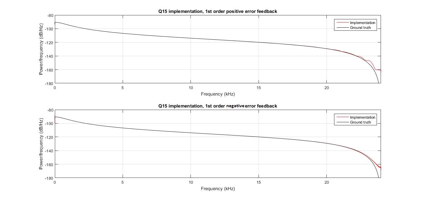
Based on that article and all the resources on the internet that advise the use of noise shaping for fixed-point filter implementations, I tried to make a few simulations on Matlab for the biquad I'm trying to implement.
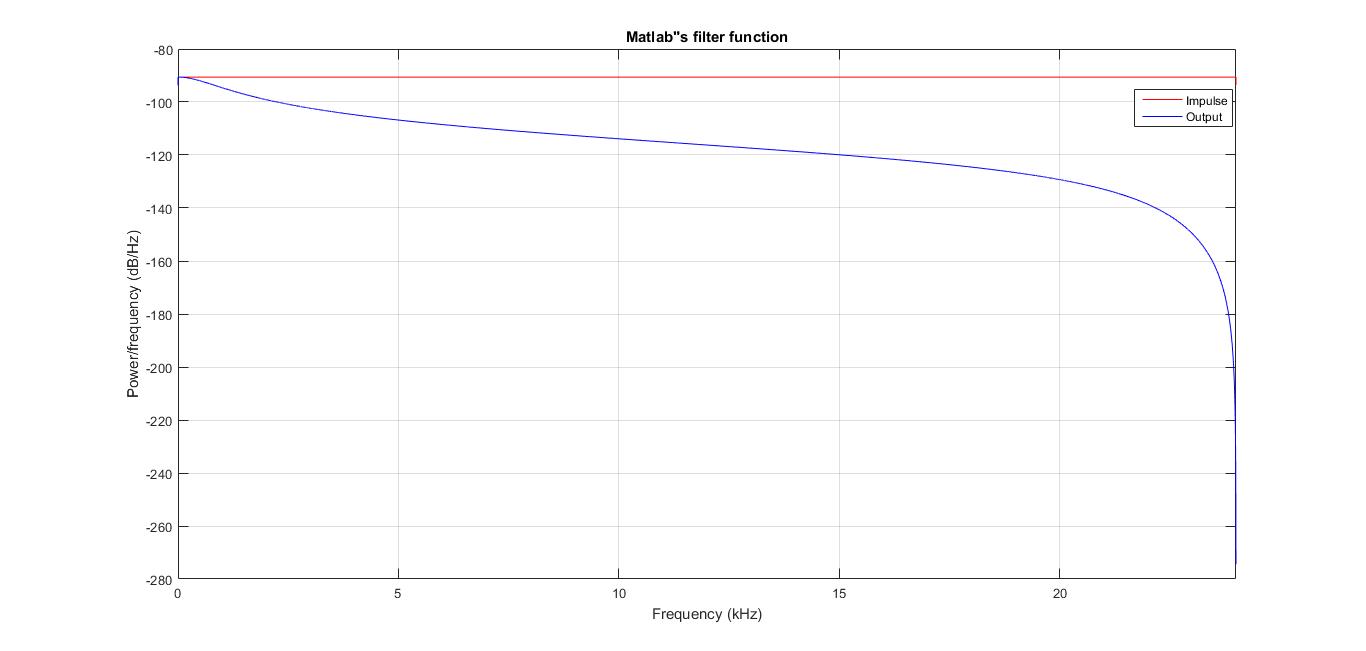
Here is my filter's frequency response using Matlab's own filter function and plotted with the periodogram function :
When I implement this filter in Q31 with no noise shaping, I get the correct frequency frequency response :
Then, as expected, the Q15 implementation introduces some errors :
Trying to reduce this error with 1st order ESS gives doutable results, although it seems close to working (I don't exactly know what to expect so I'm not sure) :

Note: I was expecting, as the document indicates (table 1), to smoothen things around 0 for positive feedback and around Nyquist for negative.
Then I tried error cancellation by multiplying the quantification error by the feedback coefficients of my biquad, and then everything turned crazy :

Here is the filtering part of my Matlab code :
acc = int32(0); % Q4.26
coeffs_Q2_13 = int16(coeffs*2^13);

sYn1 = int16(0); % Q2.13
sYn2 = int16(0); % Q2.13
sXn1 = int16(0); % Q2.13
sXn2 = int16(0); % Q2.13

X = int16(in*2^15); % float to Q2_13
Y = int16(zeros(length(X), 1)); % Q2.13
Qnoise = int16(zeros(length(X), 1));
Qnoise1 = int16(0);
Qnoise2 = int16(0);
for i = 1:1:length(X)
    acc = int32(coeffs_Q2_13(1,1))*int32(X(i));
    acc = acc + int32(coeffs_Q2_13(1,2))*int32(sXn1);
    acc = acc + int32(coeffs_Q2_13(1,3))*int32(sXn2);
    acc = acc - int32(coeffs_Q2_13(2,2))*int32(sYn1);
    acc = acc - int32(coeffs_Q2_13(2,3))*int32(sYn2);
    acc = acc + int32(coeffs_Q2_13(2,2))*bitand(int32(Qnoise1), 32767);
    acc = acc + int32(coeffs_Q2_13(2,3))*bitand(int32(Qnoise2), 32767);
    sXn2 = sXn1;
    sXn1 = X(i);
    sYn2 = sYn1;
    Y(i) = bitshift(acc, -13);
    Qnoise2 = Qnoise1;
    Qnoise(i) = int16(acc - bitshift(int32(Y(i)), 13)); %bitand(acc,     int32(8191));
    Qnoise1 = Qnoise(i);
    sYn1 = Y(i);
    acc = int32(0);
end
My filter uses these coefficients :
- ff0 = 0.04253225858264462
- ff1 = 0.08506451716528925
- ff2 = 0.04253225858264462
- fb1 = 0.21971585162695534
- fb2 = -0.6101551140424661
I'm working at Fs = 48000 and my input vector ("in" in the code) is an impulse simulated by a 48000 samples vector with the first sample being 1 and the rest 0.
What am I doing wrong?
EDIT : I've read as a comment to a question on dsp.stackexchange (to which I can't post the link due to the sus-mentionned limitations) that quantification being a non-linear process, an impulse response is not the correct way to visualize its effects. Is that the reason? should I sweep a sinewave instead?

