2
$\begingroup$

this is a basic question, but i barely find any tutorial to explain this. Most of tutorial dont talk about why use IFFT and FFT, they just say "oh, at transmitter, we just take this information time domain as frequency domain, then we need IFFT". I have no idea why we want to treat as frequency domain when it was time domain. There must be some good reasons, right?

So, why we need the FFT pair for Tx & Rx for OFDM? Why not something else ? Someone could help me with some pictures? Thank you again, friend.

$\endgroup$

4 Answers 4

3
$\begingroup$

The short answer is: Complex exponentials are eigenfunctions of an LTI system and the IFFT modulates different complex exponentials with the QAM data.

More elaborate: The wireless channel can (if it is time-invariant for the duration of one OFDM symbol) be modeled as an LTI system with impulse response $h[n]$ (in discrete-time). So, the received signal is the convolution of the input with $h[n]$. At the receiver, you want to know the data, so if you did directly transmit the data, you would need to perform a deconvolution at the receiver.

One can understand the FFT/IFFT to exploit the convolution theorem (convolution in time is multiplication in frequency). We transmit a signal in time domain at the transmitter, and transform it into the frequency domain at the receiver. Then we know, that the frequency response of the channel has multiplied the frequecy domain of the transmit signal. So, it becomes obvious that we directly define the frequency domain of the transmit signal with our QAM symbols.

This is not the whole story (circular convolution with the impulse response must be achieved such that the convolution theorem holds in discrete, and we use a Cyclic prefix to obtain it).

I've written some articles about OFDM, namely an OFDM walkthrough example and about the CP . Maybe these articles can help you understand better. I've always wanted to write something about the math behind OFDM, but didn't find the time yet.

$\endgroup$
5
  • $\begingroup$ Hello, what would happen if I use FFT to modulate the discrete data and use IFFT at receiver, with everything else kept unchanged? I think the system still works perfectly, doesn't it? $\endgroup$
    – AlexTP
    Commented Apr 13, 2017 at 6:55
  • 1
    $\begingroup$ @AlexTP: Yes, because because both $FHF^H$ and $F^HHF$ are diagonal matrices, when $H$ is a circulant matrix. $\endgroup$ Commented Apr 13, 2017 at 7:06
  • $\begingroup$ Hi, Max, I read your notes. When you say "The Cyclic Prefix converts the linear convolution into a circular convolution". Allow me to ask this, I am still not very follow. Why we need circular conv, why the linear circular is NOT ok? I think both of they will be multiplication in frequency domain, right? $\endgroup$
    – Sunson29
    Commented Apr 14, 2017 at 3:12
  • $\begingroup$ @Sunson29: Well, in the finite-time case (which we have, since you signal does not last forever), the convolution theorem states that circular convolution equals multiplication. In the infinite-time case, the convolution theorem states that linear convolution equals multiplication. So, in order to be able to exploit the convolution theorem in finite-time case, you need to have circular convolution. Maybe, my answer here also helps: dsp.stackexchange.com/questions/40157/… $\endgroup$ Commented Apr 14, 2017 at 4:12
  • $\begingroup$ Hi Max, thank you again for your help. You said " finite-time case -> circular convolution equals multiplication", but you also said "infinite-time case -> linear convolution equals multiplication". Hence, you mean, they are all = multiplication. My question, since they are the same, why I still need "in order to be able to exploit the convolution theorem in finite-time case, I need to have circular convolution"?? Thank you again, Max. $\endgroup$
    – Sunson29
    Commented Apr 14, 2017 at 16:32
2
$\begingroup$

The point is that at the transmitter side data is converted from one stream to a number of parallel streams (e.g. to achieve a higher throughput). But all those parallel streams are superimposed and transmitted on the same physical channel. So we need to multiplex different bit streams. Otherwise we cannot recover them at the receiver side.

One way (that is used in OFDM) is to divide the available bandwidth to a number of orthogonal carriers with different frequencies. So it is assumed that the input data modulates those carriers (hence it is said the data is in frequency domain). A simple way to see it is just to assume that after the bit stream is rearranged into $N$ parallel streams, each stream is associated with one frequency (so there are $N$ frequencies, or carriers in total). So we assume that there are $N$ carriers, each modulated by a data symbol. This assumption makes them separate already. Now by applying IFFT, they are converted to the time domain and then they are summed. That is, all the $N$ frequencies are available in the resulted time-domain waveform. Then the waveform is transmitted through the channel. At the receiver, we need to separate the components and demodulate them. So FFT is applied to transfer them back to the frequency domain where the same parallel symbols are obtained (which is called de-multiplexing). After that, a parallel-to-series block makes them a single bit stream again.

Note that I explained it in a simple way. In reality there are some more issues to care about.

$\endgroup$
0
0
$\begingroup$

The answer to your question lies in the following -

  1. We have QAM Complex Symbols that is required to be communicated over a certain bandwidth.
  2. We have decided that we would be using OFDM for this purpose i.e. we want to divide the available bandwidth into $N$ equally-spaced equal-width parallel non-interfering sub-channels and load each sub-channel with one QAM symbol.
  3. How can we achieve that ?

We have a very popular non-interfering pulse shape that we can use here: Sinc pulse. Remember that this has to be in frequency-domain, since the sub-channels we want is in frequency domain.

So, in frequency-domain our transmit signal will be made up of shifted Sinc-pulses such that the zero-crossing of all Sinc pulses are coinciding. In frequency-domain, shift corresponds to modulation in time-domain. So, sinc-pulse at a particular frequency is achieved by modulating a rect-window at that frequency. Mathematically, this means:

$k^{th}$ sub-channel at frequency $k\Delta f$ : $e^{j\frac{2\pi k\Delta f n}{F_s}}.rect(n), n=-\frac{N}{2},...,0,1,2,...,\frac{N-1}{2}$. Multiplication in time-domain becomes convolution in frequency domain and hence, Fourier transform of rect function which is Sinc-pulse gets shifted to $k\Delta f$ frequency.
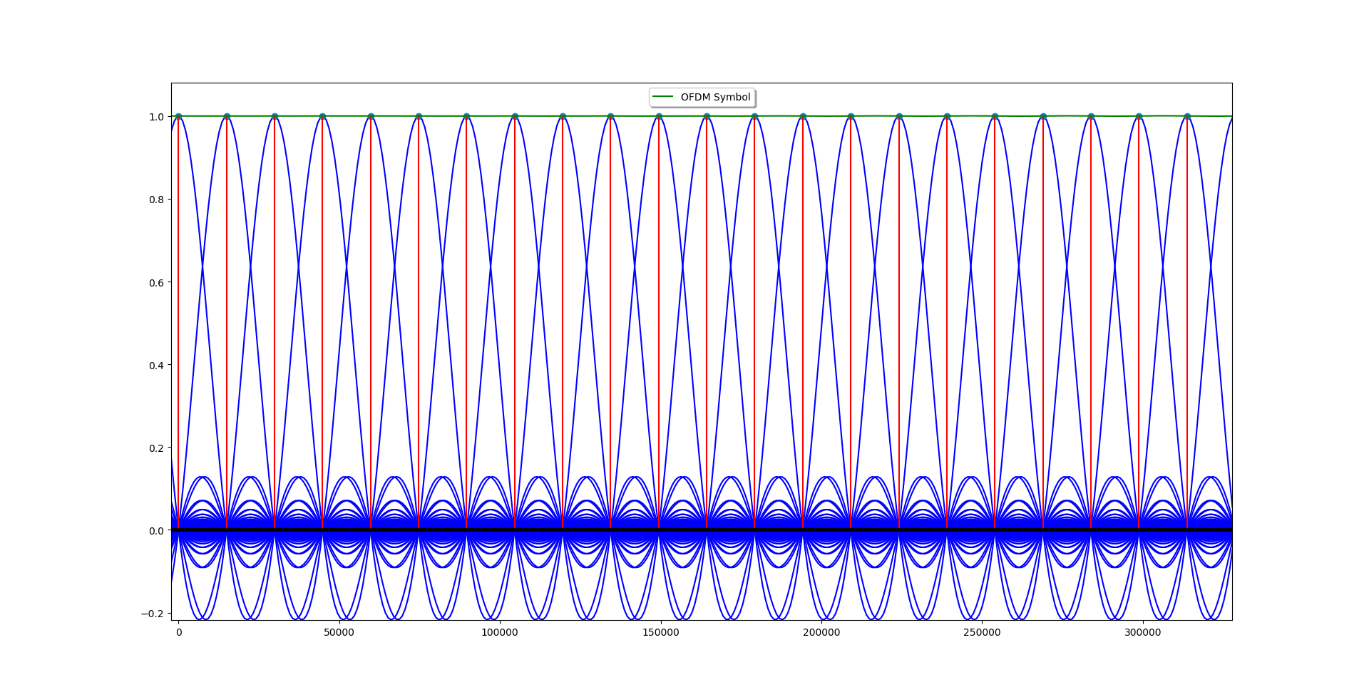
enter image description here

Now, if you look closely, $k^{th}$ sub-channel is actually $k^{th}$ Fourier Basis. So, basically, if you take $N$ QAM symbols and then take $IDFT$ of this $N$ length complex vector, you will achieve time-domain representation of $N$ sub-channels and each loaded with corresponding QAM symbol.

This resulting time-domain complex samples have to be then treated as samples at interpolating frequency $F_s = N\Delta f$

That is why we take $IDFT$ at transmitter and then to demodulate we take $DFT$ at the receiver.

$\endgroup$
0
$\begingroup$

I understand what you mean - possibly due to the complete lack of information out there that attempts to explain the situation properly. I think it is more along the lines like the following.

Consider a sequence of vectors (on paper) in the 'frequency domain'. It's really just a 'virtual' frequency domain.

This set of vectors can be complex numbers that might represent (for example) 64-QAM symbols - each vector (ie. each complex number representing a '64-QAM' symbol). But, suppose we wish to set any particular one of those vectors to zero. That's probably the catch.

When it comes time to transmit each vector by means of regular quadrature carrier (QM - quadrature modulation) technique - where the real part of the vector modulates a carrier, while the imaginary part modulates a 'quadrature' carrier - then we don't want to be transmitting a 'zero' vector - which would mean transmitting no sinusoidal carriers at all (ie. cos and sin sinusoids both zero - momentarily). This is where IFFT might help, as the IFFT of a vector sequence (where some of those vectors are set to zero) results in another sequence, where all the vectors in that new sequence (from the IFFT) contains no vectors that are zero. Then maybe at least all the vectors are not 'zero' - which may go well with quadrature carrier transmissions.

The IFFT of the virtual frequency domain sequence gives us a virtual time-domain sequence.

Naturally, the cyclic prefix needs to be added after this, which just needs to be done for dealing with multi-path channels. So adding the cyclic prefix simply results in a longer time-domain sequence. A sequence of vectors that is (ie. complex numbers). We can transmit those vectors by means of quadrature carrier modulation. The time-domain waveform that is actually transmitted has really nothing to do with physical sub-carriers at all. ie. has nothing to do with the actual frequency spectrum of the quadrature modulation waveform that is transmitted (such as wirelessly). The 'sub-carriers' actually refer to the original virtual frequency-domain vectors ----- which are only 'on paper'. It is unlike 'classical' OFDM.

Then - assuming that the system is designed so that the receiver is able to synchronise with the incoming transmission, and is able to recover the symbols that are embedded in the incoming transmission. And yes ----- synchronisation techniques, and channel estimation techniques, and training codeword symbols etc ---- may all be needed to successfully recover the time-domain vector sequence. (Also noting that cyclic prefix was used to handle multi-path effects). Recovering the time domain sequence (and removing cyclic prefix) then allows the reverse procedure to be applied. The reverse of IFFT .... which is FFT, which is meant to allow the virtual frequency-domain vector sequence to be recreated (at the receiver side that is).

$\endgroup$
1
  • $\begingroup$ Also - consider this. The output of the IFFT module is a finite length complex-valued sequence. If it is going to be transmitted, then that sequence will be pushed out once only. That sequence is not going to be transmitted in periodic (looped) fashion. So we don't expect the transmitted IFFT signal to be OFDM at all. It's just going to be quadrature modulation. That is, the physical spectrum of the 'IFFT' signal is not going to be physical 'OFDM' at all. We would expect the IFFT sequence to be looped/periodic in order to get a physical 'OFDM' spectrum. $\endgroup$
    – Kenny
    Commented Dec 5, 2023 at 7:47

Your Answer

By clicking “Post Your Answer”, you agree to our terms of service and acknowledge you have read our privacy policy.

Not the answer you're looking for? Browse other questions tagged or ask your own question.