0
$\begingroup$

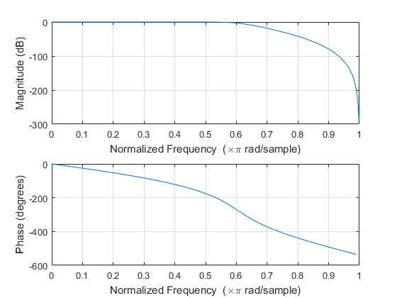
EDIT: From here (https://www.mathworks.com/help/signal/ref/butter.html) it appears that an Butterworth filter has a non-linear phase lag at the normalized frequency of 0.5 onwards. Does that mean that if the signal has multiple frequencies beyond 0.5, its output after passing through this filter will be distorted by these frequencies?

enter image description here


NOTE: To help clarify things, this question had been modified from the original one below.

A butterworth low pass filter would have a large phase lag for signals passing through at higher frequencies. [EDIT: The assumption is, for some filters to work, you'd have to do some kind of transform on the input (into the s domain), multiply that by the filter's s-domain transfer function (such as ones from here ece.uic.edu/~jmorisak/blpf.html), then to see the time-domain filtered output, the resulting output has to undergo an inverse transform.] I envision that this means that the output signal coming out of the filter, when converted back into time domain, would come out distorted due to this lag. [EDIT: The assumption is, phase lag is the same as a time delay between the input and the output, and if the input has more than one frequency component, the different components would be delayed differently, and end up being combined with another signal output at a later point in time.] Would there be similar distortions (i.e.: as if there were a phase lag) for an IIR time-domain digital filter?

$\endgroup$
4
  • $\begingroup$ What do you mean with "based on the time domain"? I usually apply butterworths in time domain... $\endgroup$ Commented Feb 23, 2017 at 7:22
  • 1
    $\begingroup$ The moment you apply filtering you change the information of the signal (even if only parts of it), unless the corner frequency is higher than the highest frequency of interest (in case of a lowpass, for example), but even then the non-ideal nature of the filter may affect the response. So, I would expect that any filter would distort, one way or another, the input signal. $\endgroup$ Commented Feb 23, 2017 at 7:35
  • $\begingroup$ That doesn't explain what you mean by "based on the time domain" at all. It does raise further questions about what you mean by distort the signal. Usually, I'd consider a signal distorted if the group delay of the filter were not constant, but you seem to be saying that filtering out high frequencies is a distortion of the signal. Obviously, this distortion would be intentional. Otherwise, why would you apply a filter? Can you explain what kind of distortion you are interested in? $\endgroup$
    – hops
    Commented Feb 23, 2017 at 7:59
  • $\begingroup$ I meant digital filters like an IIR filter, where the filtering is applied with every new time-domain data point added. I apologize, but there may be lack of knowledge on my part to ask this question properly. I thought that for some filters to work, you'd have to do some kind of transform on the input (into the s domain), multiply that by the filter's s-domain transfer function (such as ones from here ece.uic.edu/~jmorisak/blpf.html), then to see the time-domain filtered output, the resulting output has to undergo an inverse transform. $\endgroup$
    – plu
    Commented Feb 23, 2017 at 19:37

1 Answer 1

3
$\begingroup$

I think your question comes from several misunderstandings. The fact that the phase lag of a system becomes more negative for large frequencies does not mean that there's more distortion of larger frequencies. Neither does it mean that high frequency signal components experience more delay when passing through the filter.

Imagine an ideal system that simply delays the input signal while keeping its amplitude unchanged. So for an input signal $x(t)=\sin(\omega t)$ the output signal is given by

$$y(t)=\sin(\omega(t-\tau))$$

where $\tau$ is the delay. The output signal $y(t)$ can be written as

$$y(t)=\sin(\omega t-\omega\tau)=\sin(\omega t+\phi(\omega))$$

where $\phi(\omega)=-\omega\tau$ is the phase response of the system. Note that the phase becomes more negative for larger frequencies, and this is exactly what is needed for a system that does not distort the input signal.

What causes distortion are deviations of the system's magnitude response from the value $1$, and deviations of the system's phase response from the ideal linear phase shown above.

And, as mentioned in the comments, infinite impulse response (IIR) filters like a Butterworth filter are almost always implemented in the time domain. You implement a given difference equation, which is equivalent to implementing a system with a given impulse response and a given frequency response (the latter two are Fourier transformation pairs), and the phase response is part of the system's frequency response.

$\endgroup$
5
  • $\begingroup$ Doesn't phase lag mean a time delay of a signal between the input and output though? By "distortion", I meant that when a signal's input (in time domain) is compared with its output (in time domain), the assumption was that if there were some parts of the output that appear sooner, and other parts at a later time, and the parts that appear later would combine with the other output signals at that later point in time, making it appear to be different than if there were no phase lag at all. Would this assumption be correct? $\endgroup$
    – plu
    Commented Feb 23, 2017 at 19:44
  • $\begingroup$ @plu: What you describe is phase distortion due to a non-linear phase response. A linear phase response corresponds to a pure delay, hence no distortion. "Phase lag" is just a phase difference; what is important is the frequency dependence of the system's phase response. If it's non-linear, different frequency components will experience different delays, so there'll be distortion. $\endgroup$
    – Matt L.
    Commented Feb 23, 2017 at 20:43
  • $\begingroup$ Assuming a linear phase response is a straight diagonal line of phase vs. frequency (dspguide.com/ch19/4.htm), even in that case, to use a specific example, if a input signal contains two frequency components, with one frequency component having a phase lag of 90 deg. and another, 120 deg., then wouldn't that mean for the corresponding output, one part will appear 90 degs. after the input had occurred and another part appear 120 degs. after? $\endgroup$
    – plu
    Commented Feb 23, 2017 at 21:28
  • 1
    $\begingroup$ @plu: Note that phase lag is a relative quantity: 360 degrees equals one period at the given frequency. So if two frequency components have the same phase lag, then their absolute delay (measured in time units) is different. A constant phase lag (independent of frequency) actually produces distortion. $\endgroup$
    – Matt L.
    Commented Feb 23, 2017 at 21:55
  • $\begingroup$ Thanks for the clarifications, it does make sense that a shorter phase delay at a lower frequency can have the same time delay as a longer phase delay at a higher frequency, in a linear phase filter, and so no output distortion in that case. $\endgroup$
    – plu
    Commented Feb 23, 2017 at 22:51

Your Answer

By clicking “Post Your Answer”, you agree to our terms of service and acknowledge you have read our privacy policy.

Not the answer you're looking for? Browse other questions tagged or ask your own question.