This answer provides a quick introduction to decimation concepts and CIC filters which I would consider as one solution given the description.
Bottom Line First
Given your use of a microcontroller, (implied emphasis on minimizing resources), and that you indicated you do not need a high performance filter- consider doing everything with Cascade-Integrator-Comb (CIC) structures: They have unity gain coefficients and require NO multipliers! They can also provide something very important you should consider doing: decimation.
Decimate by 64:
Skipping to a possible solution for you, first decimate your signal using a 2nd Order CIC decimator such as the structure I show below, which will take your 9.5KHz signal down to a $9.5KHz/8= 1187.5$ Hz sample rate. Follow this with an identical CIC decimator to reduce the sampling rate to 148.4 Hz.

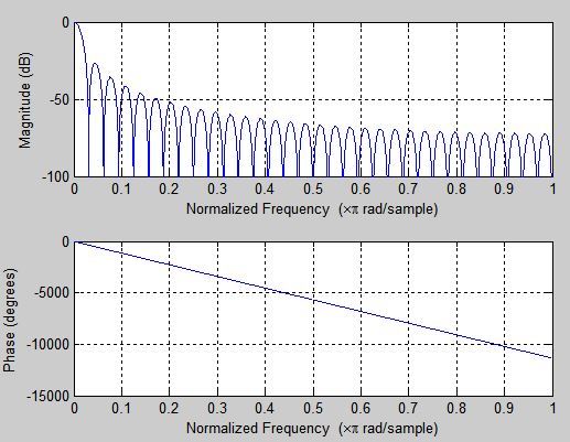
The decimator above does low pass filter the input signal, with the equivalent frequency response plotted below, relative to the input sampling rate (1 on the Normalized Frequency domain is half the sampling rate ($F_s/2$ or 4.75 KHz.). This is a pre-filter but no-where near the 8Hz cutoff desired; The first null appears at 148.4 Hz and the -3dB rejection point is at 47.5 Hz. The upper envelope of the $\textrm{sinc}^2$ response shown approximates a $1/f^2$ roll-off or 2nd order response.
Simple Moving Average LPF:
With this lower rate signal, design your 8 Hz LPF. You could consider here a simplest solution of using just a cascade of 4 sample moving averages, with some bit shifting to scale back the level, as follows:
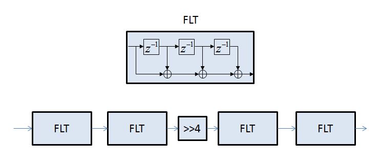
This structure will provide the response shown in the figure below, which is in addition to the broadband filtering rejection from the decimator plotted above. On the Normalized Frequency axis, 1 represents half the sampling rate, or 74.2 Hz, and 8 Hz is at 0.107. The attenuation at 8 Hz is 2.2 dB. The advantage is the simplicity (No multipliers! Unity gain coefficients!) If this filter is insufficient, then you can easily design higher performance filters, but that task is much easier at this lower sampling rate. If the concern is the passband droop, that can be compensated easily with a pre-emphasis inverse $\textrm{sinc}$ FIR filter using just 3 taps (I added a link at the bottom with details on that if interested).
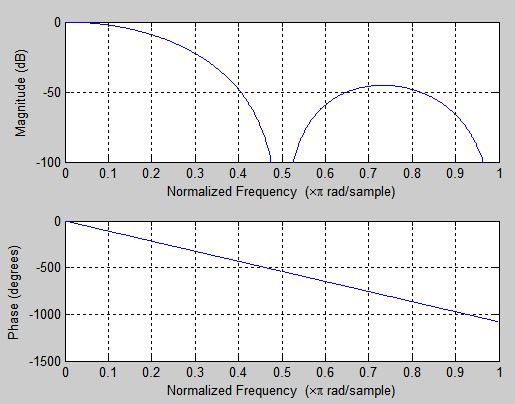
Here is another interesting option, as it has two fewer taps and better overall stopband rejection! This is the same structure above, except replace two of the four-tap FIRs with three-tap FIRs. This positions a null in the region of the dominant stopband area.
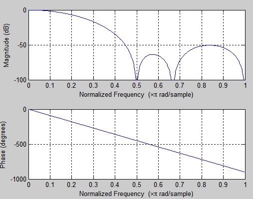
Your performance requirements may be different than what is provided by the result above; the above is to provide an example of what can be done, quite simply, with a minimum of resources, and notably no multipliers. Even a high performance implementation would use the decimation portion of this approach, (or half-band decimating filters which are also quite efficient), followed by a shaping filter which would provide the final filtering requirements desired in addition to compensation for the droop from the $\textrm(sinc)^n$ shape in the passband.
Background
CIC
Brief notes on the CIC structure shown above. (The CIC filter is also referred to as the Hogenauer Filter based on Eugene Hogenauer's 1981 paper introducing the idea). This CIC structure is two "integrators" in cascade which are simple accumulators, followed by a downsampler, which throws away all but every 8th sample, followed by two "comb filters", which is a subtraction operation between two successive lower frequency samples as shown in the figure. This one is specifically a 2nd order CIC, $(CIC)^2$, and the order can be increased by adding more integrator and comb stages (5 in a row of each would be a $(CIC)^5$ which is what you often see used in high performance systems. The higher the order, the more rejection of frequency regions that would fold into the frequency of interest (see discussion on decimation below). The accumulators cycle delay block shown ($z^{-1}$) is one clock cycle at the higher input rate, and the comb cycle delay block shown is one clock cycle at the lower output rate. This decimator will work with any value of downsampling, but as that number increases the precision needed within the accumulator and comb elements increases. I used quick judgement without detailing an actual design that it would be easier to cascade two of these overall structures to get a total decimation of 64, rather than implement it in one down-sampler element, but the number of stages and the decimation value at each stage is a knob you can play with. Important to note that the accumulators are allowed to overflow by design, but they must "roll-over" on overflow for the CIC to work properly (as opposed to saturate), meaning $cnt_{max}+n = n$. Additionally they cannot be allowed to roll-over multiple times before the subsequent subtraction operations have completed. Basically the math for the subsequent subtraction needs to be consistent regardless of a previous accumulator overflow: If the difference between samples is allowed to grow larger than the precision, the an inconsistency will result due to modulo arithmetic. For this reason I suggest you start with the 2nd order (or even a first order) as I have sketched unless you have a thorough understanding of the CIC operation.
The CIC is just a mathematical transformation of the moving average filter! It is exactly equivalent in operation to a moving average filter, it is not an approximation. In fact, the structure below is the CIC equivalent of the 4 sample moving average filter shown as "FLT" in the second figure above. Cascading multiple stages of integrators and combs is the same result as cascading multiple moving average filters (we cascaded two stages for the $CIC^2$ implementation.) What also is clear by reviewing the structure below (after convincing yourself the input and outputs would be identical to that with a 4 sample scaled moving average filter, or divide the output by 4 to get a true moving average), is if we were to use this structure as the pre-filter for a decimate by 4 (see discussion on decimation below), our first inclination would be to filter the signal with the filter as provided, and then down sample by keeping every 4th sample. If you study the "comb" portion of the filter, you can see that the downsample can be moved prior to the comb and the comb can be reduced to one delay at the lower rate- with the same result! (taking advantage of the fact that we were ignoring all but every 4th sample anyway).

Why Decimate?
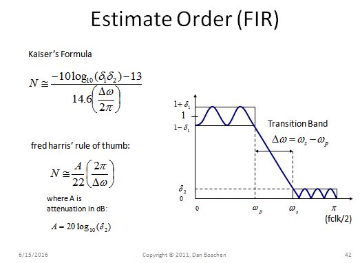
Regardless of final filter approach used, the fact that you want to make an 8 Hz low pass filter in a system with a 9.5 KHz sampling rate where resources are prime, should absolutely be decimated (meaning reduce the sampling rate digitally). This will significantly simplify your filter implementation for a given performance metric. To give some insight into this, I included a slide I had on estimating the number of taps (complexity) needed for a FIR filter. The key take-away is to notice how the number of taps is driven by the transition band, as a fraction of the sampling rate. Given the same transition in Hz, if you implement your filter with a sampling rate of 80 Hz versus 9.5 KHz, the number of taps needed to achieve the same filter decreases by a factor of nearly 120!! You may need to use the higher sampling rate elsewhere in your implementation, which is fine, but for the filter, and subsequent processing after your filter, you should highly consider running at a lower rate (multi-rate signal processing).
To properly decimate, you must filter the input signal first and then throw away samples (downsample). The filtering is important as there are bands in your overall frequency range that will fold right into your low pass signal of interest when you throw away samples, so very important to reject noise and interference at these locations. A very simple and effective way to do this, it to filter with a moving average, as it is just a summation with no multipliers and provides it's maximum rejection at all the frequency locations that would fold in. For example, if you want to decimate by 2 (reduce the sampling rate by 2), then you can sum adjacent samples in a moving average, and then throw away every other answer in the result; which is identical to doing a block by block average with 2 sample blocks. To decimate by 10, you can do a moving average over 10 samples, and then throw away all but every 10th sample in the result; which is identical to doing a block by block average with 10 sample blocks. Key point: A moving average filter (unity gain coeff FIR) has a $\textrm{sinc}$ function frequency response in frequency, with the first null at $1/T$ Hz, and subsequent nulls in integer multiples of $1/T$, where $T$ is the length of your filter in time. These null locations ARE the locations where the noise and interference folds into your "DC" area when you downsample. A CIC filter properly rejects these nulls and provides the necessary moving average for decimation. The passband droop which results can be easily compensated for with an inverse $\textrm{sinc}$ pre-emphasis filter. This inverse-$\textrm{sinc}$ filter can be easily done with a 3 tap FIR.
CIC Filter Compensation
I found this question and added an answer there detailing the simple 3-tap FIR filter I use for CIC compensation
how to make CIC compensation filter

