2
$\begingroup$

I asked exact the same here one year ago: One year ago question I asked this question again here, because after one year, I have learned more about DSP and am thinking ways to improve it.

Filter description

  • Filter input data rate is 64kHz

  • Filter output data rate is 0.5Hz - 2Hz

  • The filter is preferably to have bandwidth of 1mHz with very sharp transition area, since only DC is needed and the noises at 0-5Hz is large.

The answer I got

The averaging data is the best DC I can get. I bought this answer. However, it now becomes plausible to me, since a filter always have a bandwidth and frequency responses. Averaging is essentially a FIR with no superior characteristics.

Questions

  1. Shall the filter be designed in this way: 9 stages of halfband filters(64kHz -> 125Hz). Followed by three stages of cascaded integrator–comb (CIC) filters with R=5. Then the output will be fed into a 1st order IIR filter?

  2. Maybe 16 stages of halfband filters? (64kHz -> 0.9765625Hz) And then be fed into an IIR filter.

  3. How shall the filter be designed?

$\endgroup$

3 Answers 3

6
$\begingroup$

Your questions still leave me wondering as to what you're actually designing. For software implementation on modern x86 CPUs, CICs make almost no sense, but they are extremely elegant in hardware.

These filter definitions are ridiculous if you're planning to use a FIR – a transition width of 1mHz means that a minimum phase equiripple filter [1, (5.75), p. 142] would have

$$ N_e' \approx \frac 16 \log_{10}\left(\frac{1}{10\delta_1\delta_2^2}\right)\frac{f_s}{\Delta f} $$ taps, with $f_s$ the sampling rate, $\Delta f$ the transition width, and $\delta_{1,2}$ the passband ripple and the stopband attenuation, respectively.

Now, your use case; I'm guessing from your the graphs from your question from 1 year ago, and also bearing in mind that you'd need incredible numerical accuracy to make use of > 80dB attenuation:

$$ \begin{align*} f_s &= 6.4\cdot10^4\,\text{Hz,}\\ \Delta f &= 10^{-3}\,\text{Hz,}\\ \delta_2 &= -90\,\text{dB}\\ &= 10^{-9}\\ \delta_1 &= \delta_1\,\text{, everything else being wasteful either on suppression or precision side,}\\\\ N_e' & \approx \frac 16 \log_{10}\left(\frac{1}{10\cdot10^{-27}}\right)\frac{6.4\cdot10^4}{10^{-3}}\\ &=\frac16\cdot 26\cdot6.4\cdot10^7\\ &\approx 2.7 \cdot 10^8\,\text. \end{align*} $$

Obviously, Bellanger's approximation wasn't meant for such extreme cases, but the order of magnitude alone highlights the impossibility. Of course, you'd implement this as a decimating polyphase FIR, which means that you'd only need to apply $$\frac{N_e'}{\frac{f_{s,input}}{f_{s,output}}}=N_e' \frac{f_{s,output}}{f_{s,input}}= N_e'\frac{\frac12}{6.4\cdot10^4}\approx2110$$ tapped filter every input sample clock, but the filter length puts impossible constraints on your machine accuracy if you're using floating point, and very hard constraints if you're building this in hardware on the bitwidth of your samples. As you notice, it does make a lot of difference for what we're designing a filter here – Matlab is not hardware :)

Yes, you can split your filter into multiple stages, but that will usually only reduce the computational load by running "parts" of the filter at lower rates, and will not solve the precision/bit width problems.

So we're ditching FIRs here, unless you're willing to reduce the requirements on stopband attenuation or transition width.


On to IIRs:

There's an approximate formula for the order necessary to achieve given specifications, and that is [1, (7.18), p. 184]:

$$ N_{IIR}\approx 1.076\log_{10}\left(\frac{2}{\sqrt{\delta_1}\delta_2}\right) \log_{10}\left(\frac{f_s}{\Delta f}\frac4\pi\sin\left(2\pi\frac{f_1}{f_s}\right)\right)\text, $$ $f_1=f_2-\Delta f$ and $f_2$ being your pass- and stopband edge. Since you're lowest output rate is 0.5 Hz, I'm guessing $f_2=0.5\,\text{Hz}$.

Applying the same specifications as above, $$\begin{align*} N_{IIR}&\approx 1.076\log_{10}\left(\frac{2}{\sqrt{10^{-9}}10^{-9}}\right) \log_{10}\left(\frac{6.4\cdot10^4}{10^-3}\frac4\pi\sin\left(2\pi\frac{4.99\cdot10^{-1}}{6.4\cdot 10^{4}}\right)\right)\\ &\approx 1.076\log_{10}\left(2\cdot10^{13.5}\right) \log_{10}\left(\frac{2.56\cdot10^8}\pi\cdot4.899\cdot10^{-5}\right)\\ &\approx 1.076\log_{10}\left(2\cdot10^{13.5}\right) \log_{10}\left(3992\right)\\ &\approx 1.076\cdot13.80\cdot3.601\\ &\approx 53.48 \end{align*} $$

Note that this is but an estimate! Also notice that this is far from a design approach, it just gives us an idea of how complicated the IIR will end up being.

Now, realistically, let's round up to $N_{IIR}=64$, and then do the classical approach of directly calculation:

We'll consider elliptic filters, which are optimal in the sense that for any given order, and accepting a certain ripple (which is your DC estimate accuracy, here), they have the most narrow transition width [1, p. 183].

Now, designing these taps isn't a trivial feat; scipy gives me something that roughly looks like that:

taps (absolute values)

Notice the enormous dynamic range of each tap set ($\approx 10^{18}$), and of the overall filter ($\approx10^{65}$). That filter is nothing that reaches its accuracy on a double precision IEEE754 float.

I propose a hybrid approach: take cascaded halfband filters to get down to something like $\frac1{512}$ of the input sample rate, and then apply an elliptic filter.


1 Bellanger, Maurice: Digital Processing of Signals: theory and practice, second edition, Wiley 1988.

$\endgroup$
14
  • $\begingroup$ I am afraid that I am over-strict on defining system requirements. The system is a lock in amplifier running on a cortexM4 MCU which is 32bit with FPU. The passband could be 0.05Hz. Stop band could be at 1Hz maybe with 60dB attenuation. $\endgroup$ Commented Mar 23, 2016 at 15:24
  • $\begingroup$ Due to ignorance, I did not relate attenuation with precision. I specifies 80dB attenuation to indicate that smaller noises are preferable. Maybe 40dB is sufficient... $\endgroup$ Commented Mar 23, 2016 at 15:33
  • $\begingroup$ I wonder if what you say about CIC filters applies also to Goertzel algorithm. $\endgroup$ Commented Mar 23, 2016 at 19:40
  • 1
    $\begingroup$ Also, on an Cortex, you definitely wouldn't use a CIC if you're not extremely ROM-limited (a CIC saves coefficient storage); multiplication/addition on a float isn't that more expensive than just adding two numbers $\endgroup$ Commented Mar 24, 2016 at 9:43
  • 1
    $\begingroup$ @MarcusMüller I added a comparison table to my answer to show that halfband IIR filters can be more efficient than FIR filters with the same magnitude frequency response specification. $\endgroup$ Commented Mar 24, 2016 at 11:04
3
$\begingroup$

This answer assumes that some passband flatness is required.

Two-path all-pass half-band IIR

If you can accept the phase distortion, may I recommend the HIIR half-band lowpass filter library by Laurent de Soras. It implements half-band elliptic lowpass filters as a sum of all-pass filters that are 180° out of phase in the stop band. It is a very efficient structure that takes advantage of the symmetry of the frequency response. From the documentation:

$$\begin{eqnarray}A_0(z)&=&\prod^{\frac{N}{2}}_{k=0}\frac{a_{2k+1}+z^{-2}}{1+a_{2k+1}z^{-2}}\\ A_1(z)&=&z^{-1}\prod^{\frac{N-1}{2}}_{k=0}\frac{a_{2k}+z^{-2}}{1+a_{2k}z^{-2}}\\ H(z)&=&\frac{1}{2}\left(A_0(z)+A_1(z)\right)\end{eqnarray}$$

$A_0$ and $A_1$ are all-pass. This could be used in place of large FIR filters. Laurent doesn't recommend replacing small FIR filters when using single-instruction-multiple-data (SIMD) architecture. (I wonder if unrolling a couple of steps into a state change matrix would help with these IIR filters.) If you don't want to decimate the lowest-frequency band you can dilute the filter by substitution $z\rightarrow z^{N/2}$ for even $N$ to get $1/N$th-band filters. This has the advantage that the filter can be run in parallel in $N$ independent branches of execution with each branch calculating every $N$th output. I don't know if the library supports that other than by coefficient calculation.

HIIR is released under the most permissive Do What the Fuck You Want to Public License.

Here is a performance comparison of a linear-phase half-band FIR and a minimum-phase IIR filter like this designed to replace the FIR used in channelization in a communications satellite, taken from a conference article Adem Coskun, Izzet Kale, Richard C. Morling, Robert Hughes, Stephen Brown, and Piero Angeletti. "Halfband IIR Filter Alternatives for On-Board Digital Channelisation". 31st AIAA International Communications Satellite Systems Conference, International Communications Satellite Systems Conferences (ICSSC), (AIAA 2013-5711). DOI: 10.2514/6.2013-5711:

    RAM use     Combinational Logic 
    Power (mW)  Power (mW)  Area     Total Power (mW) 
FIR 19.44       8.35        17266    27.79
IIR 9.33        2.64        5462     11.97

Unfortunately they did not give the filter specification.

FIR vs. IIR

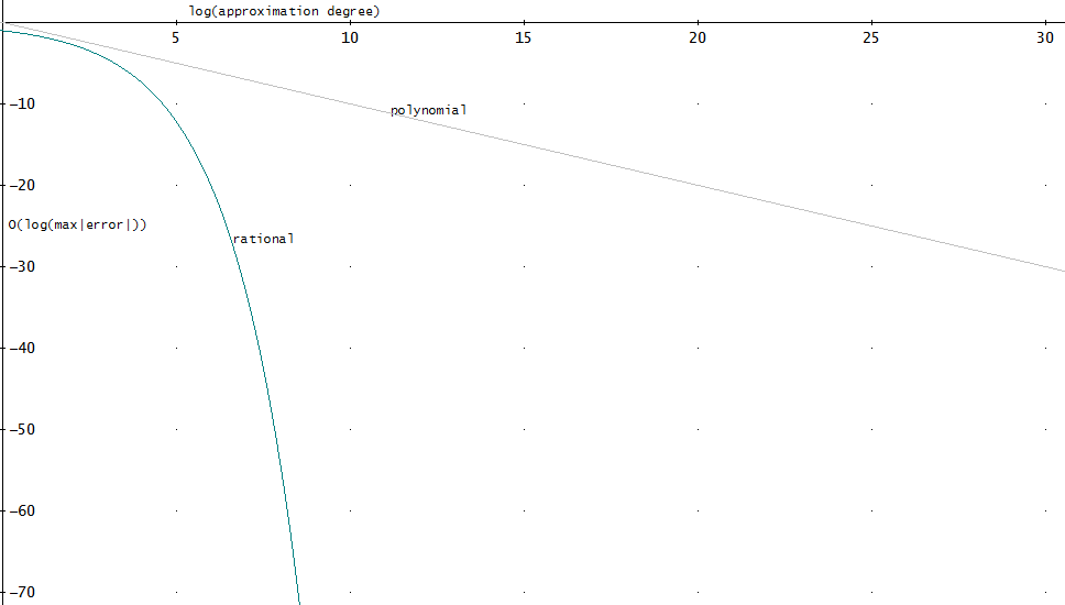
The discrete FIR transfer function is a polynomial in $z$ while the IIR transfer function is a rational function in $z$. Rational functions can better approximate functions with sharp corners. As an important example, the maximum absolute error of degree $N$ approximation of $|x|$ centered around $x=0$ by a polynomial approximation decays by $1/N$ and by a rational approximation by $\exp(-c\sqrt{N})$ with a constant $c$ (see Newman 1964), here plotted with $c=1$:

Approximation error

This doesn't say much about low-order filters but kind of implies that IIR wins over FIR for large enough filters if complexity is measured by filter order. The desired magnitude frequency response has corners similar to $|x|$ if it is defined by a passband and a stopband separated by a transition band. So the above graph would probably not change much if it compared FIR and IIR.

CIC–FIR-cascade

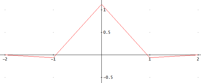
A serially connected CIC filter that implements a cascade of $M$ moving average filters of length $N$ has approximately a degree $M-1$ B-spline impulse response. This can be cascaded with a low-tap-count FIR prefilter that has a tap only at every $N$th multiple of the sampling period. I call it a prefilter because they are used as such in the context of piecewise approximation from uniform samples of a function, to reduce approximation error. Compared to a B-spline frequency response, the prefilter improves passband behavior at the cost of increased sidelobe level. For example for $M = 2$ one possible prefilter is:

$$y[k] = -\frac{1}{16}x[k-N] + \frac{9}{8}x[k] - \frac{1}{16} x[k+N],$$

derived here. I find it difficult to say what meaning its optimality properties have in the CIC–FIR context.

CIC–FIR cascade impulse response Figure 1. Impulse response of the full CIC–FIR cascade with the horizontal axis expressed as a multiple of $N$.

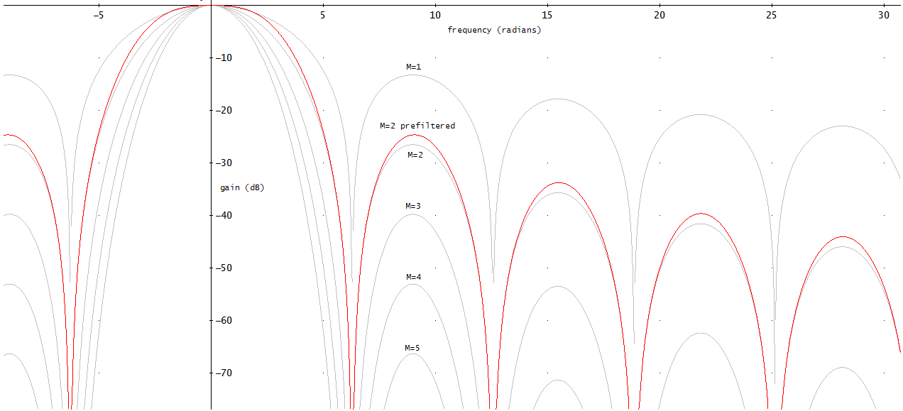
In the limit of large $N$, the shape of the frequency response of $M$ cascaded identical running average filters is the same as the frequency response of the degree $M-1$ B-spline:

$$\left(\frac{2\sin\left(\frac{\omega}{2}\right)}{\omega}\right)^M.$$

CIC–FIR cascade frequency response Figure 2. The asymptotic (as $N\rightarrow\infty$) frequency response of the CIC–FIR cascade for $M=2$ (red), with frequency expressed as a multiple of $1/N$, compared to different B-spline frequency responses (grey).

You can decide for what $M$ the frequency response is satisfactory. By increasing $M$ and by a suitable FIR prefilter similar to what I show above you can get arbitrarily close to a brickwall lowpass filter. So with a large enough $M$ you can definitely get sufficient quality.

$\endgroup$
8
  • 2
    $\begingroup$ That license is amusing. :-) $\endgroup$
    – Peter K.
    Commented Mar 23, 2016 at 19:07
  • $\begingroup$ Thanks for your answer Olli. Do you mean HIIR is more efficient than halfband FIR when orders are very high? Therefore, I could used HIIR rather than HFIR at the last stage of decimation, since that is where thin transition bandwidth is required? Also, may I ask why HIIR is more efficient than HFIR when orders are high? $\endgroup$ Commented Mar 24, 2016 at 3:19
  • $\begingroup$ @richieqianle yes, see the edit to the answer $\endgroup$ Commented Mar 24, 2016 at 7:09
  • $\begingroup$ If only clean DC value is needed, can I have your comment if averaging filters are sufficient? $\endgroup$ Commented Mar 24, 2016 at 11:29
  • $\begingroup$ @richieqianle Yes if you use a prefilter and have several running average filters in a cascade. See my recent edits to the answer. $\endgroup$ Commented Mar 24, 2016 at 12:00
0
$\begingroup$

So, in your comments to my previous answer you added a different specification; summing it up here.

Note that I assume that you'll take the cutoff frequency you specify as the sample rate coming out of your decimating filter.

Now, we first need to think about attenuation:

with -40dB you probably meant that "the total power of all the noise that gets aliased back into my passband should be attenuated by 40 dB". Now, let's act if that noise had a constant PSD, so in every frequency band there was an equal amount of noise. We're decimating by $d$ to a bandwidth $f_2$. That means that there are $d-1\approx d$ noise-containing bandwidths, each $f_2$ wide, that get aliased onto your passband. Hence, your stopband attenuation should be $d\left[\text{dB}\right]+ 40\text{ dB}$.


$$ \begin{align*} f_s &= 6.4 \cdot 10^4 \text{ Hz}\\[1.2em] f_1 &= 5 \cdot 10^{-2} \text{ Hz}\\ f_2 &= 1 \text{ Hz}\\[1.2em] \Delta f &= f_2 - f_1\\ &= 9.5 \cdot 10^{-1} \text{ Hz}\\[1.2em] d &= \frac{f_s}{f_2}\\ &= 6.4\cdot10^4\\[1.2em] \delta_1 &= -40\text{ dB}\\ &= 10^{-4}\\ \delta_2 &= \delta_1\cdot d\\ &= 10^{-4}\cdot \frac{1}{6.4\cdot10^4}\\ &= 1.563\cdot 10^-9\\ &\approx -88dB\\[1.2em] \frac{f_s}{\Delta f} &=\frac{6.4}{9.5}\,10^5\\ &\approx 6.737\cdot 10^4 \end{align*} $$ Working on an ARM-Cortex M4F

Notice that this kind of interpreting your attenuation requirements makes the attenuation even stronger than before.


FIR

Minimal phase equiripple filter $$ \begin{align*} N_e' &\approx \frac 16 \log_{10}\left(\frac{1}{10\delta_1\delta_2^2}\right)\frac{f_s}{\Delta f}\\ &\approx \frac 16 \log_{10}\left(\frac{1}{10\cdot10^{-4}(1.563\cdot10^{-9})^2}\right)\cdot6.737\cdot10^4\\ &\approx \frac 16 \log_{10}\left(\frac{1}{2.441\cdot10^{-21}}\right)\cdot6.737\cdot10^4\\ &\approx \frac 16 20.61 \cdot6.737\cdot10^4\\ &\approx 2.314\cdot10^8 \end{align*}$$

So, no, not much luck reducing the filter length by increasing transition width whilst also increasing attenuation demands.

Considering a polyphase implementation, where only $\frac 1d$ coefficients would be used per input sample, $d$ being the decimation:

$$\begin{align*} N_{e,PP}' &= \frac{N_e'}{d}\\ &\approx 3617 \end{align*} $$

3617 Floating-Point Multiply-Accumulates at the sampling rate, which happens to be $\frac1d\text{ Hz}$ means your CPU would need to do 231.4 MFlop/s (a floating point operation being an Multiplication and Accumulation combined); that's certainly in the possible range for Desktop CPUs, but definitely impossible with the Cortex M4 – you'd have to store all the coefficients (minimal phase FIR isn't symmetrical¹), and at a 32bit floating point precision, that'll be more than 882 MB of coefficient storage; your device probably won't have more than 256kB of space for that.


IIR

Now, in my last answer I used $\frac {f_1}{f_s}$ with $f_1 =4.99\text{ Hz}$; this time $f_1 = 0.05$. In this situation, Bellanger's approximation formula must fall flat.

However, let's just take the same 64 coefficient IIR, as the FIR hasn't changed length that much. And Olli's excellent answer shows that we can most likely link FIR and IIR length.

Now, the takeaway was that you'd need to be extremely clever to implement the IIR with 64bit floats; the Cortex-M4 only has hardware support for 32bit, as far as I know; that's making things a lot more complicated.


Recommendation: Cascade $\frac12$-band (Nyquist) FIRs with an IIR.

Now, with a microcontroller as target, there's no tricks such as multiplexing high-rate multiplier hardware units as in FPGAs; there's one FPU, and only a little RAM, so you'll have to write your filter with these constraints in mind:

A halfband Nyquist-M filter has only half of its taps + 1 $\ne 0$, and it can be designed symmetrical, so that you'd only need roughly one quarter of the taps of a "normal" FIR. Since RAM and fast ROM are really sparse on Cortex-M processors, that is something that you'll have to exploit.

I don't know which actual microcontroller you use, but chances are that whoever took ARM's Cortex-M4F core and used it in his silicone didn't add a memory cache controller to its RAM interface (a Cortex-M4 is a microcontroller, after all), so we can't optimize towards "cacheability", but would still much rather work on blocks of samples than on individual samples, reducing the control flow overhead (grossly oversimplifying: "do the same operation on the next 256 values, then do this operation on the resulting 128 values" is less CPU-intense than "multiply this value with a, that value with b, add that up and save it in the first output value; go back to beginning (do that 128 times)"), you'd instruct your ADC/DMA controller to give you as many consecutive samples as possible in a fixed region of RAM before triggering a CPU interrupt to process these.


¹ by the way, often you'd go for "the best FIR I can do with this architecture" on a general purpose, e.g. PC, CPU. In that case, a good rule of thumb is to go for a linear phase filter with a little less than twice as many coefficients as fit into a CPU cache line. Linear filters are symmetrical, so you can fit your whole filter into CPU cache at once, and fetching a value from RAM rather than cache typically takes $approx 100$ times the amount of time you'd spent calculating one multiply-accumulate (at least for naively programmed x86s; using hand-optimized SIMD, e.g. SSE4, you can typically increase multiplication speed, also).

Also note that, if you're using the ADC of your microcontroller, many manufacturers have an averaging filter built into the ADC controller to allow for sample-rate reduction before the samples even reach RAM.

Using the same halfband decimator sequentially first on the input rate, then on the saved half-input-rate samples, and then on the saved quarter-input-rate samples will make for a relatively efficient $2^n$ decimator, but your $n$ will be very limited by RAM (luckily, you can re-use the input sample storage space of your last stage as output of your current) and by the fact that for your 64,000 decimation, you'd need $n=15$ stages; you'd need to start pipelining things a lot so that you don't have to process the full 64,000 samples input buffer at once (which you probably won't be done with before the next bunch of samples comes in and overwrites your input...).

So, again, combine halfband FIRs with a good IIR, and come up with a clever scheduling scheme so that your data marshalling doesn't interfere with your algorithms.

Allow me one general note: When going for a decimation of 64,000, the best approach might really be an analog one; there's awesome analog filter architectures and ready-made ICs; for example, Maxim sells switched capacitance elliptic filters, which you'd have to chain with a simple one- or two-stage RC filter before connecting it to your ADC's input, and you could then really run at much lower sampling rates/ignore a lot of samples; these ICs can be configured for really low cutoff frequencies!

$\endgroup$
1
  • $\begingroup$ Hi Marcus, really appreciate your answer. I must apologize that I am very new to DSP and I could not understand most of the calculations. I will study them thoroughly tomorrow, it is late night here. Without considering the specs I gave(say 0.05Hz move to 0.5Hz), since they may be over stict due to my ignorance, what do you suggest to implement the practical most narrow low pass filter on a cortex-M4? Shall I use averaging or halfband FIRs? $\endgroup$ Commented Mar 25, 2016 at 14:28

Your Answer

By clicking “Post Your Answer”, you agree to our terms of service and acknowledge you have read our privacy policy.

Not the answer you're looking for? Browse other questions tagged or ask your own question.