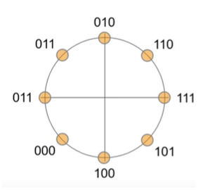
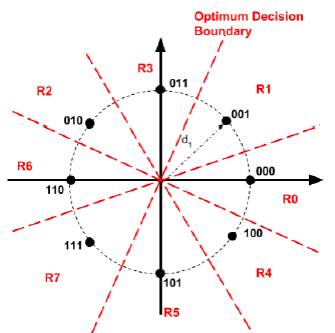
All comments and answers to this question are correct.
But there is another reason why n-PSK constellations
best not place all-zeros symbol right on 0 phase symbol:
1. Wireless channels may or may not need equalization
There are some wireless communications channels that for certain wireless channels do not need equalization.
Example
Terrestrial Trunked Radio (TETRA) Voice plus Data (V+D)
Part 2: Air Interface (AI)
TETRA with QAM mapping plus specific setting explained in the
ETSI standard 300 392-2 (TETRA Air Interface)
QUOTE
... The sub-carrier approach is used because the low symbol rate in each
sub-carrier gives the modulation inherent resistance to time dispersion hence avoiding the need for an adaptive equalizer ...
END OF QUOTE
TETRA Air Interface standard available Free download here.
2. Better be safe than sorry
But more often than not, in wireless communications, equalization is needed.
In the same TETRA standard equalization is defined so it can used when/if needed.
After all wireless channels are often time variant.
So in order to keep BER below certain threshold the Transmitter-Receiver connection has to be re-assessed and adapt to whatever is happening to the wireless channel in use.
Each transmitted symbol S corresponds to a sequence of bits.
When BER suffers degradation, hopefully before disconnection, it’s most of times because the wireless channel has changed 'too fast' or 'too much'.
We assume here no malfunction on neither Transmitter nor Receiver equipment.
No equipment operation mis-use either.
3. Probe wireless channel all the time
So when assessing a wireless channel in order to satisfy the required end-to-end bandwidth, the transfer function of the channel as well as channel noise, and interference, all have to be measured, and it's done using known sequences.
Known in advance to both Transmitter and Receiver.
- Receiver tells Transmitter 'Intial BER check' or ‘BER took a dive’
- Transmitter says ‘ok I am listening’
- then Receiver says ‘ok ready’ and
- Transmitter goes ‘starting test sequence’
In binary the easiest symbol test sequence would be 010101.. or 000111000111...
But in a constellation, to measure BER we cannot just check amplitude, we have to check phase.
It's called Bit Error Ratio but to measure BER one cannot just check single bits.
BER is measured using groups of bits, at least symbol to symbol.
Let's say S0 S1 S0 S1 .. is the symbol test sequence probing channel before sending any payload. Or through a different logic channel.
So the key point answering this question is as follows :
For a Receiver better assess phase problems, placing all-zeros symbol
On 0 phase is not as helpful as assigning test sequence S0 symbol away from zero phase, but right on the minimum phase resolution.
S0 is chosen such as S0 phase is 360/n degree (2*pi/n rad) or or 90+360/n degree ; n being total amount of symbols of nPSK constellation in use.
So S1 is 180 degree shifted from S0 plus again 360/n.
Again S1 phase is S0 minimum phase plus 180.
Note that some wireless communications may switch constellations, within same nPSK type, varying amount of points along ring, increasing or decreasing PSK ring radius, adding a second PSK ring, or even changing to QAM either to adapt to wireless channel changes and a satisfy required end-to-end bandwidth.
S0 S1 S0 S1 .. antipodal makes it easy find out channel noise in both phase and amplitude.
A small processing capacity Receiver while in the initial stage may just copy back to transmitter.
Modern smart phones can keep multiple radio channels on full payload while simultaneously measuring BER telling not just to nearest tower but to multiple near towers, all at the same time, about the quality of each wireless channel to each nearby tower. It's called soft hand-over.
GSM 2G 2nd generation had hard hand-over : each mobile was connected to only one tower during active conversation or on-going data, although other towers could tell distance by signal received from that mobile.
Mobile Operators are obliged by law to know who they deliver service to (annonymous wireless service for major carriers is illegal) and they need to know the locations of all active mobile phones to supply the agreed end-to-end bandwidth that in turn implies best possible QoS Quality of Service is being satisfied.

 I saw most examples are not in numberical order (000, 001, 010, etc.) and most of them have different order. I watched this youtube tutorial. It said mapping of state to bit is flexible. Is there any rules in drawing the bit map with phase?