0
$\begingroup$

(Context provided here, question summarized at the end.) Suppose I have an open-loop transfer function with two coincident left half plane poles like

$$ H(j\omega)=\frac{-H_0}{(1+j\omega RC)^2} $$

where $H_0>0$, and so the Bode phase plot of $H(j\omega)$ has a shape like the below (arbitrary pole and gain).

bode plots of H

If this system were put into a typical unity-gain negative feedback loop such that we form a closed-loop system

$$ A(j\omega)=\frac{H(j\omega)}{1+H(j\omega)} $$

we would expect based on the phase margin heuristic that the system would be unstable since the phase of the loop gain (here equal to $H(j\omega)$) is below -180° while $|H(j\omega)|>1$. And indeed it turns out that in this case $A(j\omega)$ has a right half plane pole on the real axis at $s=+9000$, so the impulse response is a growing exponential.

In a textbook that discusses the above example (Design of Analog CMOS Integrated Circuits, 2nd edition, p. 610), it states that the system "exhibits positive feedback near zero frequency [...] As a result, it simply 'latches up' rather than oscillates." I can see from the above results that the system does have a real-axis pole instead of a pair of complex conjugate poles and so has a pure exponential growth instead of an oscillatory one. I also see it so happens that the phase approaches -180° near DC instead of some other positive frequency.

My question: Is there some theoretical connection between the fact that the phase approaches -180° at DC and the fact that the system has a real-axis RHP pole instead of being able to achieve a pair of complex conjugate poles? Does -180° phase at DC have special significance in general? Asides from simply plotting the root locus of a given $H(j\omega)$, are there indications/suggestions from a Bode plot that the system might have real-axis RHP poles instead of complex conjugate ones?

Thanks very much for any help.

$\endgroup$

1 Answer 1

2
$\begingroup$

The formula given as $H(j\omega)$ is the frequency response, but if we are going to discuss poles and zeros for a continuous time system we would need to review the transfer function given as $H(s)$. $H(s)$ is the Laplace Transform of the system's impulse response, and from that we can get the frequency response (and therefore the Bode plot) by restricting $s$ to be $j\omega$.

That said, the OP's transfer function would be given as:

$$H(s) = \frac{-H_o}{(1+sRC)^2}$$

The significance of the phase being 180° at DC is simply the presence of the minus sign. At DC, $s=0$ and therefore $H(s=0) = -H_o$. Asssuming $H_o$ is a positive constant, the result would be 180° at DC.

As far as having complex conjugate poles in the closed loop response, we note that the closed loop transfer function is related to the open loop transfer function as follows:

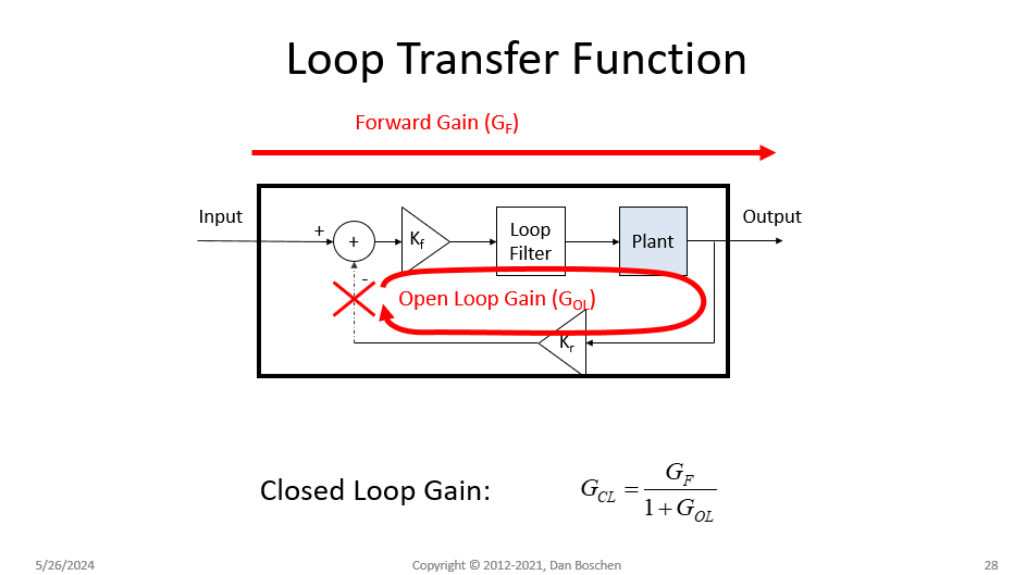
$$G_{CL}(s) = \frac{G_F(s)}{1+G_{OL}(s)}$$

Where

$G_{CL}(s)$: Closed Loop Transfer Function
$G_F(s)$: Forward Transfer Function from input to output
$G_{OL}(s)$: Open Loop Transfer Function

See my graphic below depicting each of these as a "Gain". Note importantly that the formula as given implies a negative feedback. It is possible that the negative sign the OP used is also accounting for this, in which case the Open Loop gain would just be $\frac{H_o}{(1+sRC)^2}$.

Loop Transfer Function

From this we see that the poles of the closed loop system are defined by the denominator given as $1+G_{OL}(s)$. This expression is called the "characteristic equation". To determine if the poles are complex or real, simply solve for the roots of the characteristic equation.

$\endgroup$
4
  • $\begingroup$ Thanks for your response. The quote that I posted seems to say that because the phase of H(s=0) = -180° from the negative sign in H(s) (which I meant to be separate from the negative feedback loop's negative sign), that directly implies that the closed-loop TF will have a real-axis RHP pole. I can tell from looking for numerical counter-examples that this can fail e.g. if |H(s=0)|<1, but is there a more general rule/pattern here? Of course like you mention in your last sentence, directly solving for the poles is an option but I'm wondering if some kind of heuristic could exist. $\endgroup$
    – Halleff
    Commented May 26 at 21:49
  • $\begingroup$ I think you need to be careful about any such heuristic explanations including the simplified Bode plot criterion or phase and gain. See this other post talking about the more reliable Nyquist criterion and from that you can see there can be cases of arbitrary DC gain and phase; the stability depends on the frequency response of the network so you could get any other result for a given DC value depending on what that is: dsp.stackexchange.com/questions/36055/… $\endgroup$ Commented May 26 at 22:02
  • $\begingroup$ Thanks for the additional reference. I have some familiarity with the Nyquist criterion but I'll try to review that in more detail soon. I suppose for now it seems like the answer is that there isn't a simple way to guess based on the plant's behavior near DC whether real-axis RHP poles will exist. $\endgroup$
    – Halleff
    Commented May 26 at 22:21
  • $\begingroup$ No, since we could easily come up with cases of a left or right half pole (or complex poles) for any given DC value $\endgroup$ Commented May 26 at 22:26

Your Answer

By clicking “Post Your Answer”, you agree to our terms of service and acknowledge you have read our privacy policy.

Not the answer you're looking for? Browse other questions tagged or ask your own question.