3
$\begingroup$

I am currently working on a MATLAB project where I aim to replicate the functionality of certain Phased Array System Toolbox functions (phased.ULA() and phased.PhaseShiftBeamformer()) using pure MATLAB code. I've made progress in replacing phased.ULA() as shown below:

clear all;
% Provided data
retVal = 1.0e+03 * [
    3.5040 - 0.0300i, 3.6100 + 2.9130i;
   -0.6230 + 0.0330i, -1.0960 + 1.2770i;
    1.6360 - 1.1560i, 2.4620 + 2.2290i;
    4.4610 + 2.9620i, 3.8240 + 6.1530i
];
c = 3e8;
fc = 77e9;
lambda = c / fc;
Ne = 4;
% Manually simulate ULA array response
theta = 0:pi/180:2*pi;  % Angle range
element_positions = zeros(3, Ne);
for n = 1:Ne
    element_positions(1, n) = 0; % x-coordinate
    element_positions(2, n) = (n - (Ne+1)/2) * lambda/2; % y-coordinate
    element_positions(3, n) = 0; % z-coordinate
end

However, I'm stuck at replacing phased.PhaseShiftBeamformer(), and would greatly appreciate guidance on how to proceed further in implementing beamforming techniques using pure MATLAB code. My intention is to understand the underlying mathematical concepts and signal processing techniques involved in the phased.PhaseShiftBeamformer() function.

Any insights or explanations regarding the implementation of beamforming algorithms without relying on the phased array toolbox functions would be immensely helpful.

$\endgroup$
0

1 Answer 1

3
$\begingroup$

Since you are only looking at a ULA, you only need to specify your array in one dimension (in your nomenclature, it's the y-axis). Then, the phase difference that a pair of channels will see for a signal arriving from angle $\theta$ is $-2\pi/ \lambda \cdot d \cdot \sin \theta$. From this you can easily derive the array response and steering vectors.

Code example:

%Set parameters 
fc = 77e9;
c = 2.99792458e8;
lambda = c/fc; 
Ne = 4;              %Number of elements
d = lambda/2;        %Element spacing 

%Get the element locations for a ULA
y = [0:Ne-1].'.*d;
y = y - mean(y);

%Compute the array resonse for all angles of interest 
thetas_deg = -90:0.1:90; 
r = exp(-1j*2*pi/lambda*y.*sind(thetas_deg));

%Choose a steering direction, and form the steering vector 
steerTheta_deg = 0; 
v_steer = exp(-1j*2*pi/lambda*y.*sind(steerTheta_deg)); 

%Calculate and plot the beampattern. 
%NOTE: The steering vector technically has the conjugate phase of a
%response vector for the same angle. To account for this, we use the '
%(conjugate transpose) instead of .' (transpose only)
patt = v_steer'*r;
figure; plot(thetas_deg, 10*log10(abs(patt)))
ylim([-30, 0] + 10*log10(Ne))
xlim([-90, 90])
xticks([-90:30:90])
xlabel('Angle')
ylabel('Gain')
title(['Beampattern for Electronic Steering to ' 
num2str(steerTheta_deg) char(176)])  

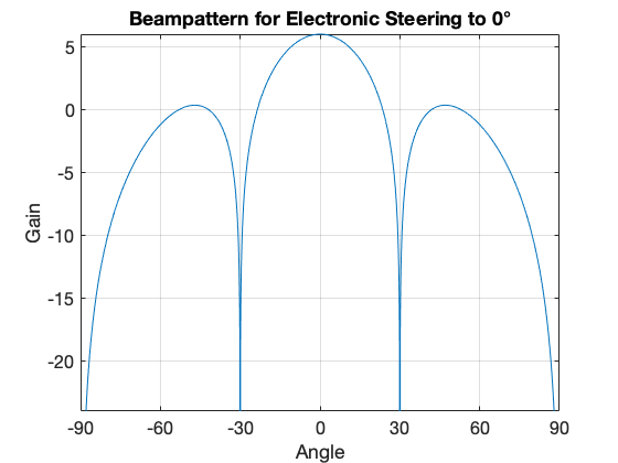
The beampattern for electronic steering to broadside (0) is: enter image description here

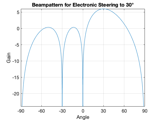
If you want to steer to another direction, set steerAz_deg to something else (e.g., 30): enter image description here

$\endgroup$

Your Answer

By clicking “Post Your Answer”, you agree to our terms of service and acknowledge you have read our privacy policy.

Not the answer you're looking for? Browse other questions tagged or ask your own question.