2
$\begingroup$

I am quite new to the VHDL domain and totally new to using its ip core. I'm trying to implement an 8 point FFT using the ip core FFT 7.1 but my results are a bit off and I cannot figure out why that is.

In python:

import numpy as np
x = [511, 1013, 310, 94, 890, 762, 20, 488]
[print(i) for i in np.fft.fft(x)]

Result:

0: (4088+0j)
1: (77.0838738653232-188.88373029032368j)
2: (1071-1193j)
3: (-835.0838738653232+391.1162697096763j)
4: (-626+0j)
5: (-835.0838738653232-391.1162697096763j)
6: (1071+1193j)
7: (77.0838738653232+188.88373029032368j) 

VHDL:

library IEEE;
use IEEE.STD_LOGIC_1164.ALL;
use ieee.numeric_std.all;
use IEEE.STD_LOGIC_UNSIGNED.ALL;

entity TestRPI is
    Port ( Clk : in  STD_LOGIC );
end TestRPI;

architecture Behavioral of TestRPI is

        signal sig_val0 : std_logic_vector(10 downto 0) := "00111111111"; --511
        signal sig_val1 : std_logic_vector(10 downto 0) := "01111110100";   --1012
        signal sig_val2 : std_logic_vector(10 downto 0) := "00100110101"; --309
        signal sig_val3 : std_logic_vector(10 downto 0) := "00001011110"; --94
        signal sig_val4 : std_logic_vector(10 downto 0) := "01101111010"; --890
        signal sig_val5 : std_logic_vector(10 downto 0) := "01011111010"; --762
        signal sig_val6 : std_logic_vector(10 downto 0) := "00000010100"; --20
        signal sig_val7 : std_logic_vector(10 downto 0) := "00111100111"; --487
    
        
        COMPONENT FFT8 is
            port(
                clk : in STD_LOGIC := 'X'; 
                start : in STD_LOGIC := 'X'; 
                fwd_inv : in STD_LOGIC := 'X'; 
                fwd_inv_we : in STD_LOGIC := 'X'; 
                rfd : out STD_LOGIC; 
                busy : out STD_LOGIC; 
                edone : out STD_LOGIC; 
                done : out STD_LOGIC; 
                dv : out STD_LOGIC; 
                xn_re : in STD_LOGIC_VECTOR ( 10 downto 0 ); 
                xn_im : in STD_LOGIC_VECTOR ( 10 downto 0 ); 
                xn_index : out STD_LOGIC_VECTOR ( 2 downto 0 ); 
                xk_index : out STD_LOGIC_VECTOR ( 2 downto 0 ); 
                xk_re : out STD_LOGIC_VECTOR ( 14 downto 0 ); 
                xk_im : out STD_LOGIC_VECTOR ( 14 downto 0 ) 
            );
        end component;
        
        signal sig_i_start, sig_i_scale_sch_we : std_logic := '0';
        signal sig_o_rfd, sig_o_busy, sig_o_edone, sig_o_done, sig_o_dv : std_logic := '0';
        
        signal sig_i_xn_re, sig_i_xn_im : std_logic_vector(10 downto 0) := (others => '0');
        signal sig_i_scale_sch : std_logic_vector( 3 downto 0 ) := (others => '0');
        
        signal sig_o_xn_index, sig_o_xk_index : std_logic_vector(2 downto 0) := (others => '0');
        signal sig_o_re, sig_o_im : std_logic_vector(14 downto 0) := (others => '0');
        
begin

    comp_fft8 : FFT8 port map (
        Clk,
        '1',
        '1',
        '1',
        sig_o_rfd,
        sig_o_busy, 
        sig_o_edone,
        sig_o_done,
        sig_o_dv,
        sig_i_xn_re,
        sig_i_xn_im,
        sig_o_xn_index,
        sig_o_xk_index,
        sig_o_re,
        sig_o_im
    );
    
    process(Clk) is
        variable var_counter : integer := 0;
    begin
        if rising_edge(Clk) then
            sig_i_start <= '1';
            if sig_o_rfd = '1' then
                if var_counter = 0 then
                    sig_i_xn_re <= sig_val0;
                elsif var_counter = 1 then
                    sig_i_xn_re <= sig_val1;
                elsif var_counter = 2 then
                    sig_i_xn_re <= sig_val2;
                elsif var_counter = 3 then
                    sig_i_xn_re <= sig_val3;
                elsif var_counter = 4 then
                    sig_i_xn_re <= sig_val4;
                elsif var_counter = 5 then
                    sig_i_xn_re <= sig_val5;
                elsif var_counter = 6 then
                    sig_i_xn_re <= sig_val6;
                elsif var_counter = 7 then
                    sig_i_xn_re <= sig_val7;
                end if;
                var_counter := var_counter + 1;
            end if;
            if var_counter > 7 then
                var_counter := 0;
            end if;         
        end if;
    end process;
end Behavioral;

Results:

0: (4085+0j)
1: (-80-187j)
2: (-1193-1072j)
3: (865+313j)
4: (625+0j)
5: (866-313j)
6: (-1193+1072j)
7: (-79+187j) 

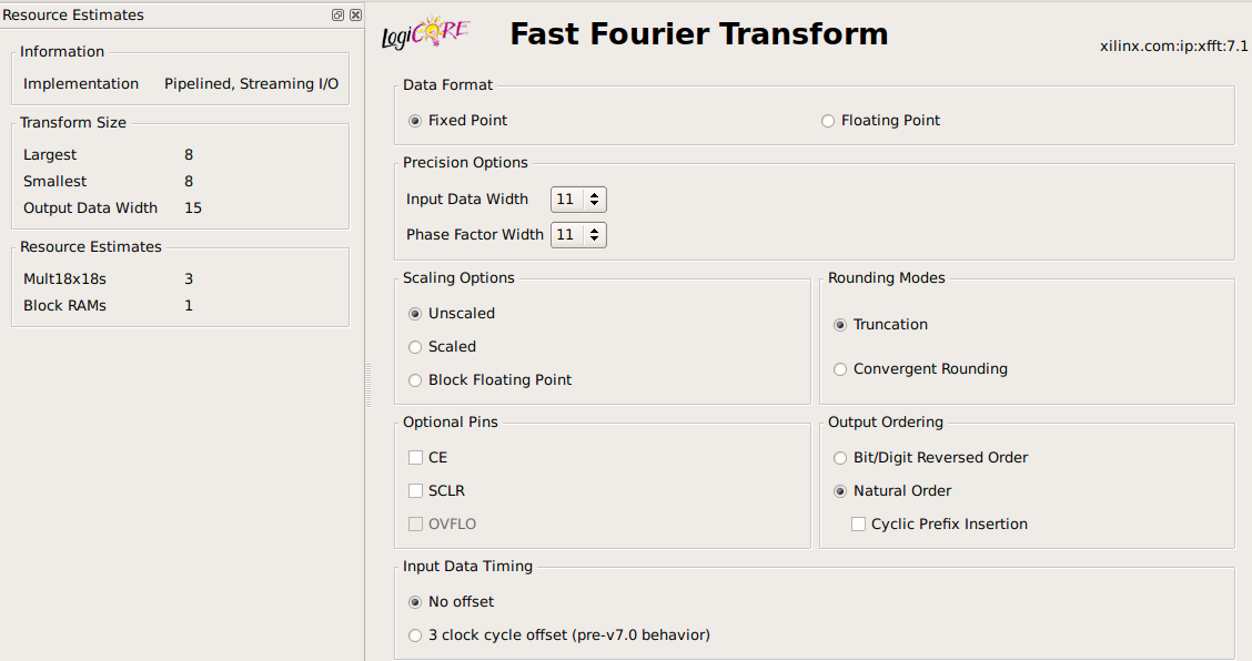
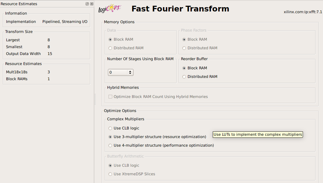
I get that my output is all integers only, which is fine. But the signs are almost all incorrect and moreover, results 2 and 6 are switched in their complex and non-complex part. I have included screenshots of my IP Core FFT setup.

In short, my question is; Why is this happening and what can I do to get the result I am expecting (the Python result is what I am expecting).

I appreciate any suggestion since currently, I do not know what to change / do.

I submitted the output of my simulation once more into this FFT but now setting fwd_inv and fwd_inv_we to '0' to make it an IFFT. those results were nothing like the original input values.

IP Core - FFT 8 - Settings page 1 IP Core - FFT 8 - Settings page 2 IP Core - FFT 8 - Settings page 3

PS. This is partly VHDL Related so must I use another stack? FFT does sound more dsp so I'm confused.

The Testbench:

-- TestBench Template 

  LIBRARY ieee;
  USE ieee.std_logic_1164.ALL;
  USE ieee.numeric_std.ALL;

  ENTITY testbench IS
  END testbench;

  ARCHITECTURE behavior OF testbench IS 


        COMPONENT TestRPI
        PORT(
            Clk : in std_logic
        );
        END COMPONENT;

        signal sig_Clk : std_logic := '0'; 

  BEGIN

        uut: TestRPI PORT MAP(
            sig_Clk
        );


     Clk_process :process
        begin
            sig_Clk <= '0';
            wait for 10 ns;
            sig_Clk <= '1';
            wait for 10 ns;
        end process;


END;

Simulation

$\endgroup$
3
  • $\begingroup$ Can you share the complete project? $\endgroup$
    – 138 Aspen
    Commented Aug 22, 2023 at 8:52
  • $\begingroup$ Could be my bad but honestly I wouldn't know what more to share. This is all relevant stuff to recreate my issue? $\endgroup$
    – Mart
    Commented Aug 22, 2023 at 9:32
  • $\begingroup$ I did add the testbench, maybe that helps a bit more to replicate. $\endgroup$
    – Mart
    Commented Aug 22, 2023 at 12:09

2 Answers 2

2
$\begingroup$

Have you referred to the official documentation?

See your_project_name\ipcore_dir\your_named_component_name\doc\

xfft_ds260.pdf also has its online copy.


The most practical method to verify the result is to use c model:

Bit-accurate C models for the core can be downloaded from the Xilinx Fast Fourier Transform IP Core webpage.

Details of how to use the models can be found in the core datasheet.

I don't find c model for Fast Fourier Transform v7.1, I only have xfft_v9_1_bitacc_mex.

The result is roughly consistent with your numpy.fft.fft result.

import numpy as np
x = [511, 1013, 310, 94, 890, 762, 20, 488]
[print(i) for i in np.fft.fft(x)]

Result:
0: (4088+0j)
1: (77.0838738653232-188.88373029032368j)
2: (1071-1193j)
3: (-835.0838738653232+391.1162697096763j)
4: (-626+0j)
5: (-835.0838738653232-391.1162697096763j)
6: (1071+1193j)
7: (77.0838738653232+188.88373029032368j) 

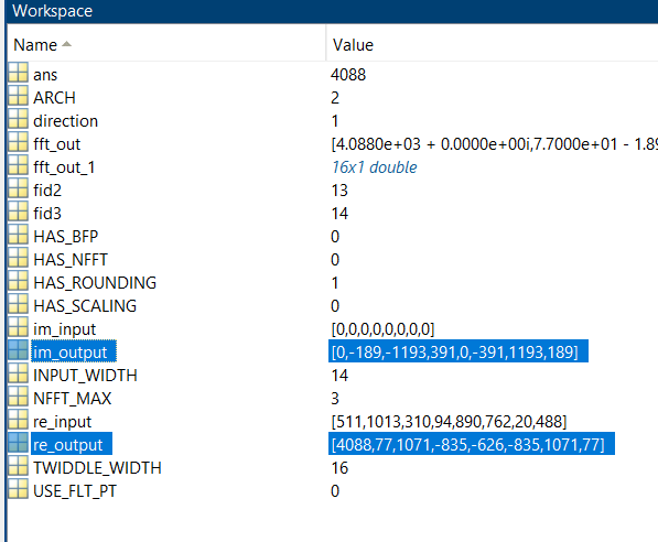
enter image description here


I shared the project here.

How to use it? unzip, then run fft_sim_example.m with MATLAB

Some key parameters are:

direction=1;
NFFT_MAX=3;
ARCH=2;
HAS_NFFT=0;
USE_FLT_PT=0;
INPUT_WIDTH=14;
TWIDDLE_WIDTH=16;
HAS_SCALING=0;
HAS_BFP=0;
HAS_ROUNDING=1;
$\endgroup$
1
  • $\begingroup$ Thanks for this very elaborate answer! Let me install matlab now to go about myself but in the meantime I do have a few questions. 1) I can see that your result is as expected, but how can I translate that into VHDL? Since I'm wondering, how can I pass on those key parameters to my vhdl component or ip core setup. $\endgroup$
    – Mart
    Commented Aug 22, 2023 at 9:48
1
$\begingroup$

I might call myself stupid, or you might. But anyway the answer has been found.

The reason that the results were of was because of the offset. In the settings (see original question), the offset was set to zero. In my VHDL code I thought I had a zero offset as well but as it turned out, I had a offset of 1 by default due to the signal delays of one clock cycle. I changed the offset in the settings to 3. In my VHDL code I changed the offset in such a manner that I could match xn_index and now the simulation is perfect.

Datasheet that shows the offset: Offset (Thanks @aspen, I should've read more carefully)

New VHDL:

library IEEE;
use IEEE.STD_LOGIC_1164.ALL;
use ieee.numeric_std.all;
use IEEE.STD_LOGIC_UNSIGNED.ALL;

entity TestRPI is
    Port ( Clk : in  STD_LOGIC );
end TestRPI;

architecture Behavioral of TestRPI is
        type t_array_in is array(0 to 9) of std_logic_vector(10 downto 0);
        signal sig_in_re : t_array_in := (others => (others => '0'));
        signal sig_in_im : t_array_in := (others => (others => '0'));
    
        COMPONENT FFT8 is
            port(
                clk : in STD_LOGIC := 'X'; 
                start : in STD_LOGIC := 'X'; 
                fwd_inv : in STD_LOGIC := 'X'; 
                fwd_inv_we : in STD_LOGIC := 'X'; 
                rfd : out STD_LOGIC; 
                busy : out STD_LOGIC; 
                edone : out STD_LOGIC; 
                done : out STD_LOGIC; 
                dv : out STD_LOGIC; 
                xn_re : in STD_LOGIC_VECTOR ( 10 downto 0 ); 
                xn_im : in STD_LOGIC_VECTOR ( 10 downto 0 ); 
                xn_index : out STD_LOGIC_VECTOR ( 2 downto 0 ); 
                xk_index : out STD_LOGIC_VECTOR ( 2 downto 0 ); 
                xk_re : out STD_LOGIC_VECTOR ( 14 downto 0 ); 
                xk_im : out STD_LOGIC_VECTOR ( 14 downto 0 ) 
            );
        end component;
        
        signal sig_i_start, sig_i_scale_sch_we : std_logic := '0';
        signal sig_o_rfd, sig_o_busy, sig_o_edone, sig_o_done, sig_o_dv : std_logic := '0';
        
        signal sig_i_xn_re, sig_i_xn_im : std_logic_vector(10 downto 0) := (others => '0');
        signal sig_i_scale_sch : std_logic_vector( 3 downto 0 ) := (others => '0');
        
        signal sig_o_xn_index, sig_o_xk_index : std_logic_vector(2 downto 0) := (others => '0');
        signal sig_o_re, sig_o_im : std_logic_vector(14 downto 0) := (others => '0');
        
begin

    comp_fft8 : FFT8 port map (
        Clk,
        '1', -- start
        '1', -- fwd/inv
        '0', -- fwd/inv we
        sig_o_rfd,
        sig_o_busy, 
        sig_o_edone,
        sig_o_done,
        sig_o_dv,
        sig_i_xn_re,
        sig_i_xn_im,
        sig_o_xn_index,
        sig_o_xk_index,
        sig_o_re,
        sig_o_im
    );
    
    process(Clk) is
    begin
    
        sig_in_re(0) <= "00111111111"; --511
        sig_in_re(1) <= "01111110100";  --1012
        sig_in_re(2) <= "00100110101"; --309
        sig_in_re(3) <= "00001011110"; --94
        sig_in_re(4) <= "01101111010"; --890
        sig_in_re(5) <= "01011111010"; --762
        sig_in_re(6) <= "00000010100"; --20
        sig_in_re(7) <= "00111100111"; --487
        
        if rising_edge(Clk) then
            sig_i_start <= '1';
            
            if sig_o_rfd = '1' then
                sig_i_xn_re <= sig_in_re((to_integer(unsigned(sig_o_xn_index)) -2) mod 8);
                sig_i_xn_im <= sig_in_im((to_integer(unsigned(sig_o_xn_index)) -2) mod 8);
            end if; 
        end if;
    end process;
end Behavioral;

For completeness I added a screenshot of my simulation results. The blue lines (input / xn and xn_index) show the offset clearly. 511, the first sample, is given at xn_index = 3.

simulation results

$\endgroup$

Your Answer

By clicking “Post Your Answer”, you agree to our terms of service and acknowledge you have read our privacy policy.

Not the answer you're looking for? Browse other questions tagged or ask your own question.