1
$\begingroup$

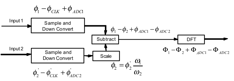
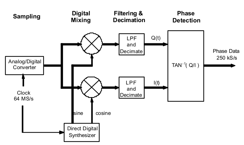
The direct-digital phase noise measurement technique is described in "Direct-Digital Phase-Noise Measurement" by Grove (DOI:10.1109/FREQ.2004.1418466, PDF link). The basic architecture of this technique, for 1 DUT and 1 reference channel, is shown in the following two block diagrams.

enter image description here

enter image description here

In the 2nd image, the "Sample and Down Convert" block is the block diagram in the first image.

In that 2nd image, the reference phase is scaled by the ratio of DUT to reference frequency. Why is that done?

Here's my understanding of the signals and noise terms. Consider an input DUT signal:

$$ \begin{equation} x(t) = a(t) \cos[\omega_{\mathrm{dut}} t + \phi_{\mathrm{dut}}] \end{equation} $$

When this is sampled by an ADC it incurs additional phase noise due to sampling clock jitter and ADC (mostly quantization) noise. Therefore, the signal after the ADC (ignoring its discrete nature for now) is

$$ \begin{equation} x'(t) = a \cos (\omega_{\mathrm{dut}} t + \phi_{\mathrm{dut}} + \phi_{\mathrm{adc}} + \phi_{\mathrm{clk}}). \end{equation} $$

To demodulate this signal to baseband, we multiply it by a quadrature NCO signal

$$ \begin{equation} n(t) = e^{i \omega_{\mathrm{nco}} t}. \end{equation} $$

The result of this multiplication is

$$ \begin{align} x'(t) n(t) &= a \cos (\omega_{\mathrm{dut}} t + \phi_{\mathrm{dut}} + \phi_{\mathrm{adc}} + \phi_{\mathrm{clk}}) e^{i \omega_{\mathrm{nco}} t},\\ &= \frac{a}{2} \left[\exp[i (\omega_{\mathrm{dut}} t + \phi_{\mathrm{dut}} + \phi_{\mathrm{adc}} + \phi_{\mathrm{clk}})] + \exp[-i (\omega_{\mathrm{dut}} t + \phi_{\mathrm{dut}} + \phi_{\mathrm{adc}} + \phi_{\mathrm{clk}})]\right] e^{i \omega_{\mathrm{nco}} t},\\ &= \frac{a}{2} \left[\exp(i [(\omega_{\mathrm{dut}} + \omega_{\mathrm{nco}}) t + \ldots]) + \exp(i [(\omega_{\mathrm{nco}} - \omega_{\mathrm{dut}}) t + \phi_{\mathrm{dut}} + \phi_{\mathrm{adc}} + \phi_{\mathrm{clk}}])\right]. \end{align} $$

The $\omega_{\mathrm{dut}}+\omega_{\mathrm{nco}}$ term is at a high frequency and is filtered out. This leaves

$$ \begin{equation} x'(t) n(t) = \frac{a}{2} \left[\exp(i [(\omega_{\mathrm{nco}} - \omega_{\mathrm{dut}}) t + \phi_{\mathrm{dut}} + \phi_{\mathrm{adc}} + \phi_{\mathrm{clk}}])\right]. \end{equation} $$

We can extract the phase of this from the 2-argument arctangent function, leaving

$$ \begin{equation} \phi_1 (t) = (\omega_{\mathrm{nco}} - \omega_{\mathrm{dut}}) t + \phi_{\mathrm{dut}} + \phi_{\mathrm{adc}} + \phi_{\mathrm{clk}}. \end{equation} $$

If $\omega_{\mathrm{nco}} = \omega_{\mathrm{dut}}$, $\phi_1 (t) = \phi_{\mathrm{dut}} + \phi_{\mathrm{adc}} + \phi_{\mathrm{clk}}$ (this won't in general be exactly true, but I think it's ok for this analysis).

If we did this for the 2nd channel too, we'd have

$$\begin{align} \phi_1 (t) &= \phi_{\mathrm{dut}} + \phi_{\mathrm{adc1}} + \phi_{\mathrm{clk}},\\ \phi_2 (t) &= \phi_{\mathrm{ref}} + \phi_{\mathrm{adc2}} + \phi_{\mathrm{clk}}. \end{align} $$

I don't see anything that indicates those phase terms depend on the carrier frequency and need to be scaled prior to subtraction.

$\endgroup$
2
  • $\begingroup$ ah, the early 2000s, when doing benign-sized FFTs on 30 MS/s was still a problem… $\endgroup$ Commented Aug 21, 2023 at 21:30
  • $\begingroup$ I do have serious questions about their 2tan⁻¹ function; the accuracy of which is no children's game $\endgroup$ Commented Aug 21, 2023 at 21:31

1 Answer 1

1
$\begingroup$

In that 2nd image, the reference phase is scaled by the ratio of DUT to reference frequency. Why is that done?

When you want to measure a 30 MHz oscillator, but only have a 10 MHz reference source, then (in the absence of noise), the 30 MHz's oscillator's phase would grow three times as fast as the phase of the 10 MHz reference oscillator. Frequency is the derivative of phase over time!

So, scaling the phase with a factor of 3 essentially just multiplies the frequency of the reference oscillator by the same factor. I haven't checked whether they also discuss this in the paper, but it of course also scales the phase noise variance by a factor of 3² = 9 (generally, the square of the factor).

So, unless your reference oscillator has very signifanctly better phase noise than your sample clock and your device under test, that can become problematic.

The classic solution to that is having a mid- to long-term frequency-stable reference clock, and using a PLL controlling a short-term stable oscillator.

(Which really raises the question of: if you have a good reference source, why not use it to synthesize sample clock, and just numerically derive a "perfect" mixer frequency; this might be an issue of availability of low-jitter frequency synthesizers for sample clock generation, then again, you can directly, with very integer factors directly derive a sample clock. Hm.)

Anyways, your assumption

If $\omega_{\text{nco}} = \omega_{\text{dut}}$

hence fails here; $\omega_{\text{nco}} = \omega_{\text{dut}} / m$, with some $m\in\mathbb N$.

As they say on the second page:

However, if the two input signals have different nominal frequencies…

!!


Remarks, since too long for comments:

We can extract the phase of this from the 2-argument arctangent function, leaving

Yep, but watch what you're doing here, stochastically. The distribution of the error you do when estimating phase through atan2 (which is really $\Im\{\ln(\dots)\}$) is different than the distribution of the error before. (This sometimes ends in Cauchy-distributed variables. Something that is awful to deal with, as that's a distribution without finite variance.)

Depending on what went in there as distributions, you can hence get quite an amplification of noise variance that way, or quite a reduction (I wouldn't bet on the latter, but I'm too tired).

$\endgroup$
7
  • $\begingroup$ The NCOs can be set independently for the DUT and reference channels. So, the phase of each channel, not ignoring frequency drift, is $\phi_1 (t) = (\omega_{\mathrm{nco(dut)}} - \omega_{\mathrm{dut}}) t + \phi_{\mathrm{dut}} + \phi_{\mathrm{adc1}} + \phi_{\mathrm{clk}}$ and $\phi_2 (t) = (\omega_{\mathrm{nco(ref)}} - \omega_{\mathrm{ref}}) t + \phi_{\mathrm{ref}} + \phi_{\mathrm{adc2}} + \phi_{\mathrm{clk}}$. Sorry, I probably could have been clearer on this point. Anyway, I do think $\omega_{\mathrm{nco(dut)}}=\omega_{\mathrm{dut}}$, etc. Or at least approximately so. Or did I misunderstand? $\endgroup$
    – MattHusz
    Commented Aug 21, 2023 at 23:20
  • $\begingroup$ Well the sentence from the paper that I quote directly contradicts that, and the phase factor does, too. $\endgroup$ Commented Aug 21, 2023 at 23:23
  • $\begingroup$ Hm, I still don't follow. If, using their example of a 10 MHz DUT and 5 MHz ref, we downconverted both channels using a 10 MHz I/Q DDS and LPF'd and decimated, the band around the reference carrier would be completely filtered out. Scaling isn't performed until after phase detection. Bear with me here, I expect I'm just still not understanding what you (and the paper) are saying... $\endgroup$
    – MattHusz
    Commented Aug 21, 2023 at 23:32
  • $\begingroup$ They're directly determining the phase velocity of the mixture product. So unless you want a phase that spins with the difference in frequency, you need to make the reference phase spin as fast as the phase of dut. So, you achieve exactly that by multiplication of the slower-by-a-factor-of-$m$ phase with $m$. $\endgroup$ Commented Aug 21, 2023 at 23:41
  • $\begingroup$ Ok I think I now understand that part. Thanks for taking the time to explain and re-explain. So would you then, later (eg after subtraction), compensate to nullify the change in the phase noise variance caused by scaling? $\endgroup$
    – MattHusz
    Commented Aug 22, 2023 at 0:32

Your Answer

By clicking “Post Your Answer”, you agree to our terms of service and acknowledge you have read our privacy policy.

Not the answer you're looking for? Browse other questions tagged or ask your own question.