(I will be referring to info from these slides in this post, for your reference.)
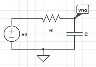
Consider first for comparison a typical CT low-pass filter, without any sampling, for example implemented by the RC circuit below.
Here the CT input source $v_n(t)$ with transform $V_n(s)$ is the noise generated by the resistor. The noise is attenuated by the filter at the output according to the transfer function
$$ V_{no}(s) = \frac{1}{1+RCs}V_n(s) = H(s) V_n(s) $$
The resistor's thermal noise has a one-sided PSD $S_n(f)=4kTR$. We also have a theorem (whose name I don't know) that $S_{no}(f)=|H(f)|^2S_n(f)$. By Parseval's theorem, $\overline{v_{no}(t)^2}=\int_0^\infty S_{no}(f) \, df$. Substituting in, we arrive at the typical result that $\overline{v_{no}(t)^2}=kT/C$.
Now, consider the same circuit except with a switch that implements a track-and-hold response, as illustrated below. (Located at slides 25 and 26 in the PDF). $\phi$ indicates the clock signal controlling the switch: when $\phi$ is high, the switch is on and the output tracks the input. When $\phi$ is low, the switch is off and the output is disconnected from the input and held constant.
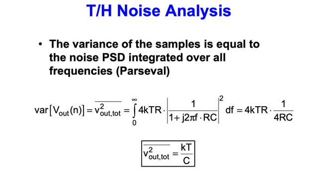
Now I would like to consider the discrete-time sequence of samples $v_{out}[n]$ as illustrated in the figure, and I would like to find the quantity $\overline{v_{out}[n]^2}$. This is the average value of the squared time-domain output samples, where again this output is due to the noise alone. The lecture slides perform the following derivation (slide 28):
In other words, it's exactly the same as the completely continuous-time case, both in the steps taken and the final result. Why is this the case? Is there a rigorous justification for why this correct or is there an implicit approximation here? How is the discrete-time nature of the samples being taken into account? If this assumes instantaneous settling of the output once the tracking phase starts, how would one go about a more exact derivation?


