1
$\begingroup$

I am working on the implementation phase and time recovery algorithm and have doubts. Could you please explain to me some question?

  1. PLL for time and phase recovery

I have found I can use PLL not only for a carrier phase correction but also for time. Is there difference in implementation?

Reference: Digital communications a discrete-time approach by Rice

  1. what should be first: phase or time recovery?
$\endgroup$
2
  • $\begingroup$ could you be slightly more specific about your reference? A PLL, as the name suggests, controls a phase, not a time, so you can't use a PLL to correct time. A PLL might be part of a larger system used to estimate timing offset, but that is something different. $\endgroup$ Commented Mar 30, 2021 at 20:20
  • $\begingroup$ Re: 2.: That completely depends on the time and phase correction you want to do, and the channel that you're dealing with. There's no "one fits all" solution. $\endgroup$ Commented Mar 30, 2021 at 20:20

2 Answers 2

1
$\begingroup$

I like the Rice's book as it gives enough details and explanations to be able to get to working implementation with a full understanding of what is actually happening. So the following is basically a citation from Rice.

1. What are the differences in PLL implementation?

A phase locked loop (PLL) in general has three basic components: a phase detector, a loop filter and a voltage controlled oscillator (VCO) arranged in a feedback system (see Appendix C in Rice's book). Digital PLL will have a somewhat similar structure. The goal of the PLL is to force the phase error to be zero.

Any PLL holds this basic structure. But for the tasks of synchronization (carrier and timing recovery) the particular implementation of PLL will depend on the algorithm you choose for a phase detector. Also it differs in where the feedback connection of the PLL goes.

2. What should be first: carrier or timing recovery?

In the section "10.1 Advanced Discreet-Time Architectures" Rice gives the review of different receiver architectures. For example, this is a "third generation discrete-time detector":
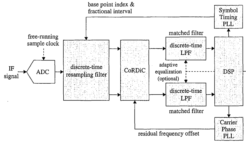
Rice, third gen receiver

It shows the placement of PLLs for carrier recovery and symbol timing. Here you can see, that corrections from Symbol Timing PLL occur before the ones from Carrier Phase PLL. Note, that Rice also describes other architectures, which differ in where the feedback connections go.

$\endgroup$
2
  • $\begingroup$ if there is a big frequency offset, could TED be first? my big problem is a frequency offset ( doppler). It is big. $\endgroup$
    – Jang Lee
    Commented Apr 1, 2021 at 7:45
  • $\begingroup$ @JangLee Yeah, my answer is too general for your underlying problem, isn't it? Unfortunately, I don't have enough experience with this to help you yet. You should definitely either edit your question to add those details, or create a new follow-up question. Don't keep it in the comments, because now your question is as general as given answers. $\endgroup$
    – megasplash
    Commented Apr 1, 2021 at 9:12
1
$\begingroup$

A receiver needs to synchronize on those two timings in order to demodulate with best performance:

  • Transmitter symbol rate
  • Transmitter carrier

Synchronization state of the art way is to use a PLL. You need two loops processing at the same time. The same PLL architecture can be used for both synchronizations but instantiated separately. That is the case for the filtering part of the loop.

Except:

  • Each loop has a different timing error detector: One detects symbol rate error and the other carrier phase error. Different algorithms for each.
  • The feedback correction is applied in different areas in the chain: Symbol rate feedback is applied on a resampler, carrier error correction where the frequency translation is done.

Also important, a PLL is a fine synchronization. Which means that if you have a too large offset it won't be able to synchronize alone. A process ahead in the chain should perform the coarse synchronization.

Timing error detector for each loop should be smartly selected. As they can interfere between themselves. For example Gardner when applicable is able to estimate the symbol rate timing error with a carrier phase offset inside.

$\endgroup$
4
  • $\begingroup$ i have a big frequency offset because of Doppler and have a problem with phase estimation. I have checked PLL ( linear and digital), costas loop...it doesn't work for my scenario. $\endgroup$
    – Jang Lee
    Commented Apr 1, 2021 at 7:48
  • $\begingroup$ What kind of modulation do you use? What is your Doppler shift range and rate? $\endgroup$
    – user51024
    Commented Apr 1, 2021 at 8:49
  • $\begingroup$ BPSK, f_doppler more 3 kHz $\endgroup$
    – Jang Lee
    Commented Apr 2, 2021 at 12:57
  • $\begingroup$ what is coarse synchronization? could you give more derails? $\endgroup$
    – Jang Lee
    Commented Apr 6, 2021 at 6:53

Your Answer

By clicking “Post Your Answer”, you agree to our terms of service and acknowledge you have read our privacy policy.

Not the answer you're looking for? Browse other questions tagged or ask your own question.