5
$\begingroup$

I'm attempting to design an FIR filter that approximates the Hilbert transform in order to get a $90^{\circ}$ phase shift and unity gain. However, I'm having trouble adjusting the filter to make it causal. I've already read this answer, which was very helpful. Here's what I've got so far.

import numpy as np
import matplotlib.pyplot as plt
from scipy.signal.windows import hamming

N = 50
H = hamming(2 * N + 1)


def coeff(n):
    if n == 0:
        return 0
    return H[int(n + N - 1)] * (2 / np.pi) * (np.sin(np.pi * n / 2) ** 2 / n)


def freq(w):
    return np.sum(
        [coeff(n) * np.exp(-1 * 1j * w * n) for n in range(-N, N + 1)]
    )


if __name__ == "__main__":
    freq_vals = np.linspace(0, np.pi, 1000)
    freq_resp = [np.abs(freq(w)) for w in freq_vals]
    ang_resp = [np.angle(freq(w)) for w in freq_vals]
    # plot frequency response
    plt.plot(freq_vals / np.pi, freq_resp)
    # plot phase shift
    plt.plot(freq_vals / np.pi, ang_resp)
    plt.show()

coeff computes an ideal hilbert transform coefficient using the equation

$$ h[n] = \begin{cases} \frac{2}{\pi}\frac{\sin^2(\pi n/2)}{n} && n\neq 0,\\ 0 && n = 0,\\ \end{cases} $$

which I've taken from Discrete-Time Signal Processing (3e) p.959. I've restricted $n\in[-50,50]$. Additionally, it applies a Hamming window to reduce the Gibbs phenomenon (see the linked answer above).

freq then computes the frequency response for a provided frequency value, using the equation

$$ H(\omega) = \sum_{n=-\infty}^{\infty} h[n]e^{-in\omega}. $$

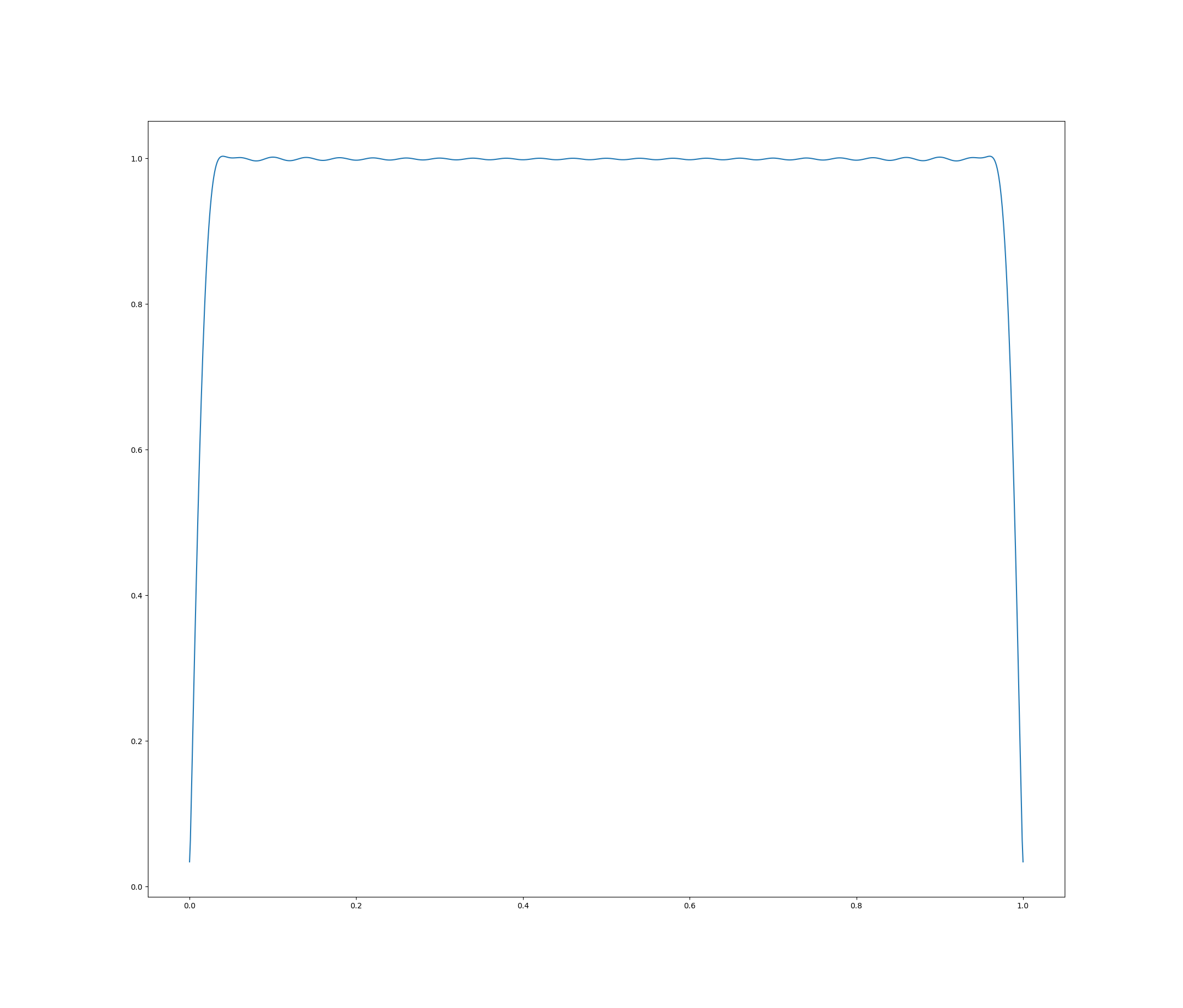
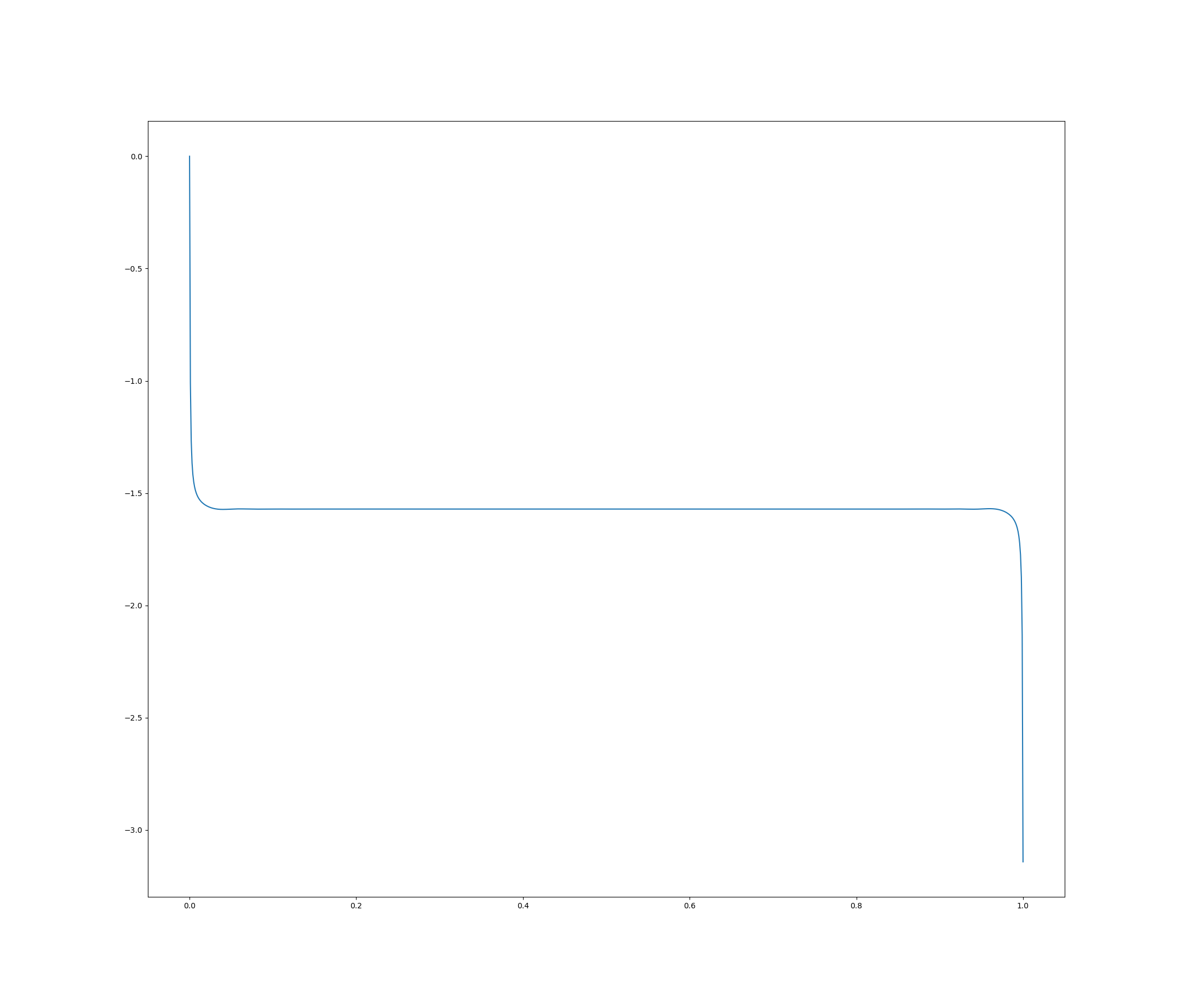
Now, when I plot this (plt.plot lines), I get the magnitude and phase response I expect:

mag (x range is 0 to $\omega$, which I've normalized to 1): enter image description here
phase: enter image description here

However, I computed the impulse response values for $h[-50],h[-49],\ldots,h[50]$. So, this filter is not causal. I believe this filter should be time-invariant, so I attempted to simply shift it so that $n$ would now range from 0 to $2N+1$. Here's the adjusted freq function:

def freq(w):
    return np.sum(
        [coeff(n - N) * np.exp(-1 * 1j * w * n) for n in range(0, 2 * N + 1)]
    )

This produces the same frequency magnitude response, but with the following "incorrect" phase response: enter image description here
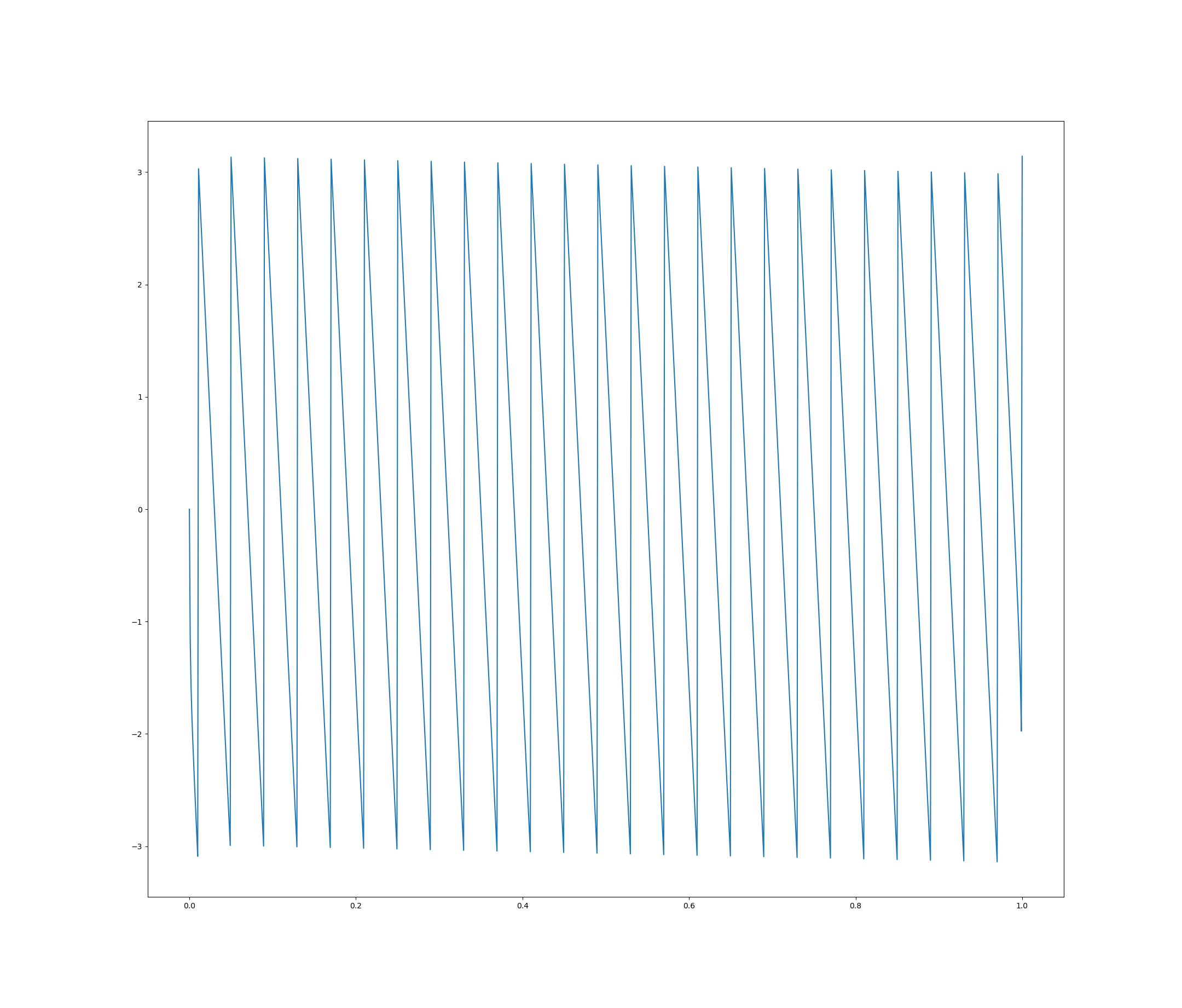
I expect I've misunderstood something fundamental about this process but I'm not sure what. How can I make this filter causal with the desired phase response? Why does my attempt to make the filter causal keep the correct magnitude response but not phase response?

$\endgroup$
5
  • $\begingroup$ Are you using this to create two signals in quadrature? Typically there is a compensating delay in the other path for the number of samples you will shift to make the signal causal, such that that path has a linear phase and this path has the same linear phase + 90° $\endgroup$ Commented Sep 25, 2020 at 3:10
  • $\begingroup$ So basically just shift the other path that this is in reference to by the same number of samples that you shifted this one to be causal (all realizable filters have a delay you just want to keep the relationship between the related signals to be 90° so simply adjust the delay of that other path whatever it may be). $\endgroup$ Commented Sep 25, 2020 at 4:15
  • $\begingroup$ @DanBoschen, that’s correct this is for two signals in quadrature. Ok, so if I understood you correctly, all I need to do is to delay both signals by $N=50$ samples. Then I can apply this filter as I would if I hadn’t created a delay but knew what the future sample values would be. Then if I’m using these signals to demodulate a 3rd noisy signal I would just delay that signal by the same 50 samples. $\endgroup$
    – MattHusz
    Commented Sep 25, 2020 at 17:05
  • $\begingroup$ Nevermind, I think my last comment is a little off. The procedure seems to be to wait for enough input signal so that I can apply the convolution to the "future" inputs. I.e., $y[0] = x[50]h[-50]+x[49]h[-49]+\ldots+x[0]h[0]$. Then, to line up the input and output (which will make them $90^{\circ}$ out of phase) I need to delay the input by 50. This same delay would need to be applied to any other signals I might want to use these two signals in quadrature to demodulate. I believe this is what you described in your comments, but please correct me if I'm wrong. $\endgroup$
    – MattHusz
    Commented Sep 25, 2020 at 20:41
  • $\begingroup$ yes I think you follow- for example if you had a signal and now want two copies in quadrature. The same signal goes to your Hilbert filter for one path and a compensating 50 sample delay (if that is the offset you used for the other path— fairly simple) $\endgroup$ Commented Sep 25, 2020 at 21:09

1 Answer 1

1
$\begingroup$

Basically, Hilbert transformers are, by definition, non-causal, always. Any zero-phase filter is non-causal. We can shift the impulse in time but the phase then becomes linear and not flat (a function of frequency).

To be implemented, the input signal must be delayed by the amount that is half the length of the filter minus one (N in this case). Or one can convolve the input signal with the impulse of the Hilbert (windowed, as you did, to minimize Gibbs). Never done the latter so check yourself.

BUT! There is a configuration that uses a pair of 4th order allpass filters that turn out to be pretty close to 90 degrees out of phase with one another. Unfortunately, the phase of each output differs from the original but depending on what you need, it can be hacked...

Reference: https://www.dspguide.com/ch19/4.htm, Design Hilbert filter at matlab (pure 90 phase and magnitude 0db)

$\endgroup$
1
  • 1
    $\begingroup$ How high an order your IIR filters need to be (or how many taps you need in your FIR filters) is a function of how broad a frequency range you need the filter to work over, and how accurate you need it to be in phase, phase difference between the channels, magnitude, and magnitude difference between the channels. The basic idea of a pair of all-pass IIR filters is a good one, IMHO, but 4th-order isn't magic -- it's just what fit the particular problem at hand (i.e., it's probably good for voice over SSB radio). $\endgroup$
    – TimWescott
    Commented Sep 25, 2020 at 16:26

Your Answer

By clicking “Post Your Answer”, you agree to our terms of service and acknowledge you have read our privacy policy.

Not the answer you're looking for? Browse other questions tagged or ask your own question.